Кондиционеры Daikin EKCBX-BBV3 - инструкция пользователя по применению, эксплуатации и установке на русском языке. Мы надеемся, она поможет вам решить возникшие у вас вопросы при эксплуатации техники.
Если остались вопросы, задайте их в комментариях после инструкции.
"Загружаем инструкцию", означает, что нужно подождать пока файл загрузится и можно будет его читать онлайн. Некоторые инструкции очень большие и время их появления зависит от вашей скорости интернета.


Installation manual
18
EKCBX/H008BBV3
Unit for air to water heat pump system
4PW66983-1C – 08.2011
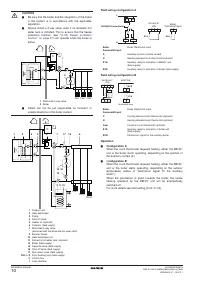
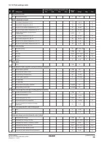
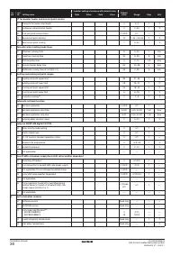
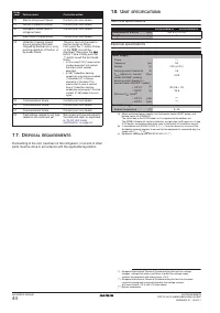
11.8. Requirements for indoor unit field wiring
Selection and sizing should be done in accordance with the
applicable legislation based on the information in the table below:
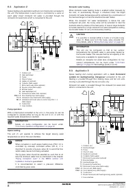
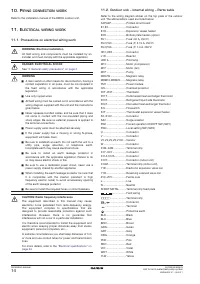
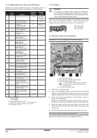
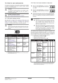
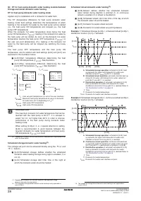
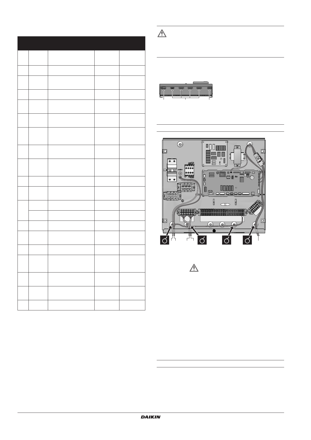
11.9. Routing
The indoor unit has several openings on the bottom side for field
wiring. Use the appropriate opening to route the high voltage, low
voltage and power supply wires as shown in the figure below.
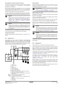
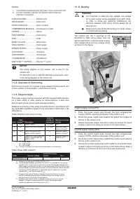
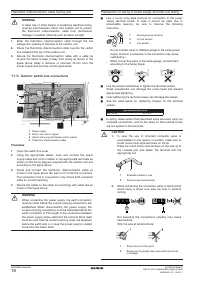
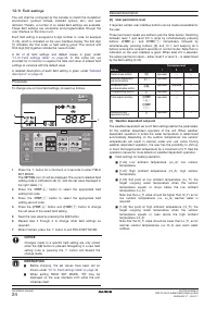
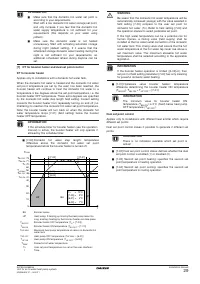
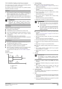
11.10.Indoor switch box connections
Connection of control signals and thermistor cable
1
Indoor unit control signals
2
Indoor unit pump and heater control signals
3
Thermistor interconnection cable
4
In case no EKHW* option with booster heater is
installed, connect an extra ground wire to the
ground terminal.
5
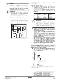
Normal kWh rate power supply
1
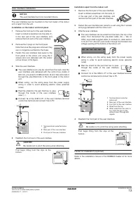
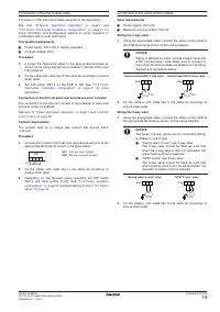
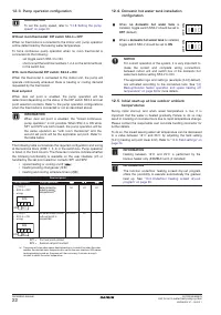
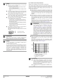
Remove the control box cover.
2
Using the appropriate cables, route and connect the control
cables to the appropriate terminals as shown on the wiring
diagram supplied with the unit and according to the figure above.
3
Route and connect the thermistor interconnection cable as
shown in the figure above.
Be sure not to force the connectors. The connectors lock in one
position only. Check both connector sides for correct matching.
4
Route the cables through the cable holders and secure the
cables to the cable tie mountings with cable ties as shown in the
figure above.
5
Close the control box cover. Take care not to pinch any wires.
Connection heater kit signals (if applicable)
Refer to the installation manual of the EKMBUH heater kit.
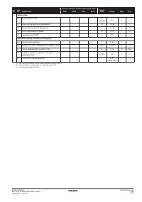
Item
Cable
bundle
(a)
(a) PS = Power supply
HV = High voltage
LV = Low voltage
Desciption
Required
number of
conductors
Maximum
running
current
1
HV
Indoor unit control signals
3 + GND
Minimum
cable section
2.5 mm
2
2
HV
Indoor unit pump and
heater control signals
4
1.25 A
(b)
(b) Minimum cable section = 0.75 mm
2
3
LV
Thermistor
interconnection cable
(supplied with unit)
8
Supplied with
the unit
4
HV
Heater kit control signals
(only for EKMBUH)
5
5
LV
Heater kit R12T
thermistor (only for
EKMBUH)
2
6
HV
Alarm output (only for
EKRP1HB* and
EKSOLHWAV1 option)
2
7
HV
Cooling/heating on/off
output (only for
EKRP1HB* and
EKSOLHWAV1 option)
2
8
HV
Solar input (only for
EKRP1HB*and
EKSOLHWAV1 option)
2
9
LV
Changeover to boiler
output (only for
EKRP1HB* and
EKSOLHWAV1 option)
2
10
HV
2-way valve (only for
EKCBX* units)
2
11
HV
Room thermostat (only for
EKRTW, EKRTR1 or
EKRTETS option)
1, 3, 4 or 5
12
LV
user interface mounted on
indoor unit front panel
–
LV
user interface mounted
apart from indoor unit
2
(c)
(c) Cable section 0.75 mm
2
till 1.25 mm
2
, maximum length: 50 m
13
HV
3-way valve (only for
EKHW option)
3
14
HV
Solar pump and thermal
protector (only for
EKSOLHWAV1 option)
2
15
LV
R5T Tank thermistor (only
for EKHW option)
2
16
HV
Booster heater power
supply and thermal
protector (only for EKHW
option)
4 + GND
(d)
(d) Refer to the nameplate of the domestic hot water tank
17
HV
Domestic hot water tank
thermal protector (only for
EKHWSU option)
2
18
PS
Booster heater power
supply (only for EKHW
option)
2 + GND
19
PS
Normal kWh rate power
supply
2 + GND
(e)
(e) Cable section = 2.5 mm
2
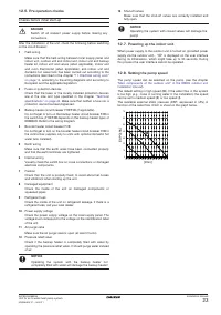
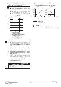
WARNING
It is important to keep the high voltage, low voltage and
power supply wiring separated from each other. In order to
avoid any electrical interference the distance between both
wiring should always be at least 25 mm.
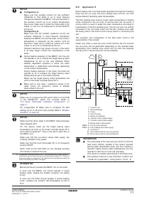
PS/HV
HV
LV
PS
Power supply
HV
High voltage
LV
Low voltage
X4M
X14M
SS2
1
2
4 5
F2B
X3M
FU1
X13A
X9A
X
15M
X2M
FU2
3


