Кондиционеры Daikin EKCBH-BBV3 - инструкция пользователя по применению, эксплуатации и установке на русском языке. Мы надеемся, она поможет вам решить возникшие у вас вопросы при эксплуатации техники.
Если остались вопросы, задайте их в комментариях после инструкции.
"Загружаем инструкцию", означает, что нужно подождать пока файл загрузится и можно будет его читать онлайн. Некоторые инструкции очень большие и время их появления зависит от вашей скорости интернета.


EKCBX/H008BBV3
Unit for air to water heat pump system
4PW66983-1C – 08.2011
Installation manual
15
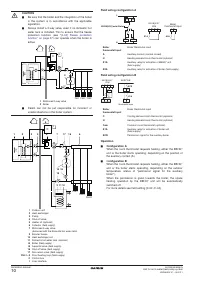
NOTES
OUTDOOR UNIT ...................Outdoor unit
INDOOR UNIT .......................Indoor unit
HYDRO MODULE .................Hydro module
COMPRESSOR MODULE ....Compressor module
OPTION .................................Option
FIELD WIRING ......................Field wiring
PCB .......................................PCB
WIRE COLOUR .....................Wire colour
FIELD SUPPLY ......................Field supply
POWER SUPPLY ..................Power supply
(OUTDOOR) ..........................(Outdoor)
(DISCHARGE) .......................(Discharge)
(CONDENSOR) .....................(Condensor)
ONLY FOR *** OPTION .........Only for *** option
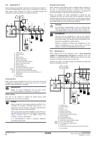
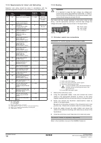
11.3. Overview of field wiring
Field wiring consists out of power supply (always including earth) and
indoor-outdoor communication (=transmission) wiring.
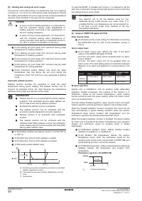
11.4. Requirements
The power supply must be protected with the required safety devices,
i.e. a main switch or other means for disconnections, a slow blow
fuse on each phase and an earth leakage protector.
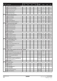
Selection and sizing of the wiring should be done in accordance with
the applicable legislation based on the information mentioned in the
table below:
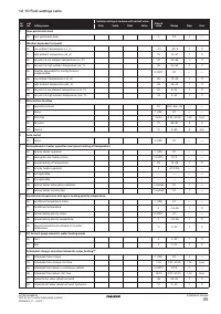
Table: Selection and sizing of wiring
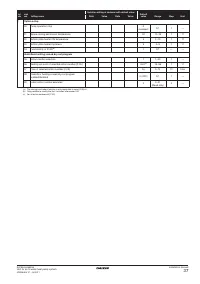
Table: Power cable selection
(1) European/International Technical Standard setting the limits for harmonic
currents produced by equipment connected to public low-voltage systems
with input current >16 A and
≤
75 A per phase.
(2) European/International Technical Standard setting the limits for voltage
changes, voltage fluctuations and flicker in public low-voltage supply
systems for equipment with rated current
≤
75 A.
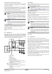
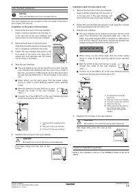
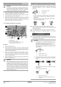
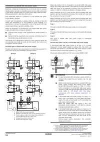
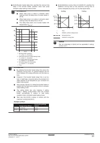
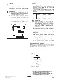
11.5. Routing
The outdoor unit has 2 openings at the
backside for field wiring intake. Use the
appropriate hole to route the power supply,
high voltage wiring and low voltage wiring
as shown in the figure.
Power supply routing (PS)
1.
Enter the power supply wire through the high voltage/power
supply (HV/PS) opening at the back of the outdoor unit.
2.
Route the power supply wire towards the switch box located at
the top of the outdoor unit.
3.
Secure the power supply wire with a cable tie around the frame
to keep it away from piping as shown in the figure above.
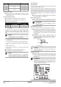
Control signal routing (HV)
1.
Enter the control signal wires through the high voltage/power
supply (HV/PS) opening at the back of the outdoor unit.
2.
Route the control signal wires towards the switch box located at
the top of the outdoor unit.
3.
Secure the control signal wires with a cable tie around the frame
to keep it away from piping as shown in the figure above. Keep a
distance of minimum 25 mm from the power supply wire.
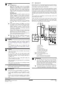
1
THIS WIRING DIAGRAM ONLY APPLIES TO THE OUTDOOR UNIT
4
DO NOT OPERATE THE UNIT BY SHORT-CIRCUITING ANY
PROTECTION DEVICE
NOTICE
The wiring diagram on the outdoor unit is only for the
outdoor unit.
For the indoor unit or optional electrical components, refer
to the wiring diagram of the indoor unit.
Item
Cable
bundle
(a)
(a) PS = Power supply
HV = High voltage
LV = Low voltage
Description
Required
number of
conductors
Maximum running
current
1
PS
Power supply
2 + GND
18 A
2
HV
Indoor unit control signals
3 + GND
Minimum cable
section 2.5 mm
2
3
HV
Indoor unit pump and
heater control signals
4
Minimum cable
section 0.75 mm
2
4
LV
Thermistor interconnection
cable (supplied with the
outdoor unit)
8
Supplied with the
outdoor unit
(b)
(b) If wiring is damaged, the cable shall be replaced by an original one.
Model
Nominal voltage
Maximum running
current
Z
max
EBHQ+EKCB
(a)(b)
(a) Equipment complying with EN/IEC 61000-3-12
(b) This equipment complies with EN/IEC 61000-3-11
provided that the system
impedance Z
sys
is less than or equal to Z
max
at the interface point between the
user's supply and the public system. It is the responsibility of the installer or user
of the equipment to ensure, by consultation with the distribution network operator
if necessary, that the equipment is connected only to a supply with a system
impedance Z
sys
less than or equal to Z
max
.
1x 230 V
18 A
0.42
Ω
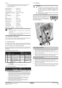
WARNING
■
It is important to keep the high voltage, low voltage
and power supply wiring separated from each other.
In order to avoid any electrical interference the
distance between both wiring should always be at
least 25 mm.
■
Make sure to secure the field wiring so it never comes
in contact with any piping.
LV
PS
HV
LV
PS HV
LV
LV
PS
PS
HV
HV
LV
PS
HV


