
Коммутаторы D-Link DGS-1010MP/A1A - инструкция пользователя по применению, эксплуатации и установке на русском языке. Мы надеемся, она поможет вам решить возникшие у вас вопросы при эксплуатации техники.
Если остались вопросы, задайте их в комментариях после инструкции.
"Загружаем инструкцию", означает, что нужно подождать пока файл загрузится и можно будет его читать онлайн. Некоторые инструкции очень большие и время их появления зависит от вашей скорости интернета.


3
E
N
G
LI
S
H
Hardware Installation
Before You Begin
Observe the following precautions to help prevent
shutdowns, equipment failures, and personal injury:
• I nstall the DGS-1010MP in a cool and dr y
place. Refer to the technical specifications in
the user manual for the acceptable operating
temperature and humidity ranges.
• Install the switch in a site free from strong
electromagnetic sources, vibration, dust, and
direct sunlight.
• Leave at least 10 cm of space to the left and right-
hand side of the switch for ventilation.
• Visually inspect the power connector and make
sure that it is fully secured to the power cord.
• Do not stack any devices on top of the switch.
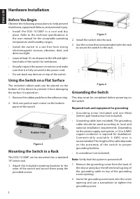
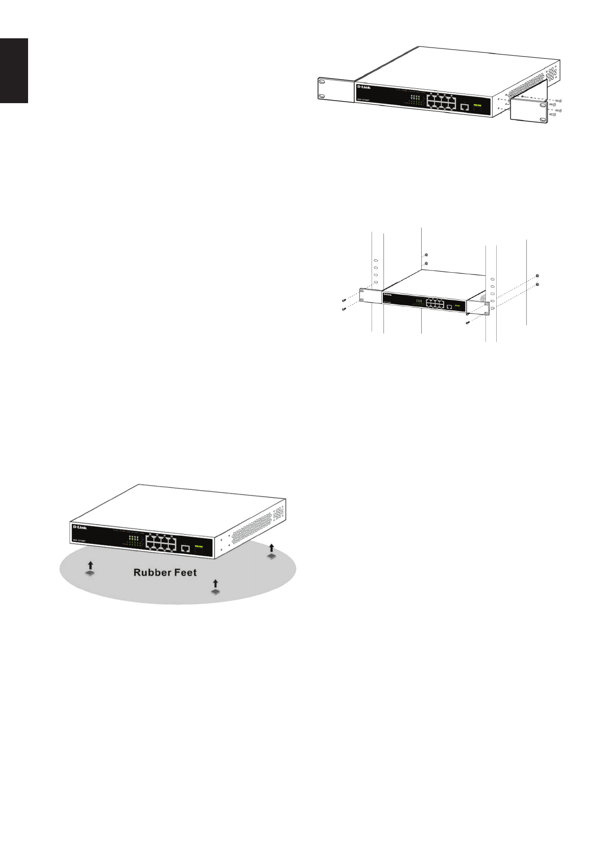
Using the Switch on a Flat Surface
The included rubber pads can be placed on the
bottom of the device to prevent it from damaging
the surface it is placed on.
1. Remove the rubber pads from the adhesive strip.
2. Stick one pad on each corner on the bottom
panel of the switch.
Figure 4
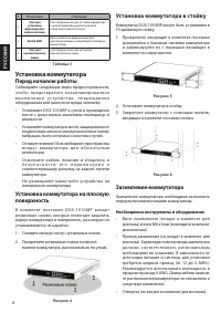
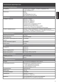
Mounting the Switch in a Rack
The DGS-1010MP can be mounted into a standard
19” server rack.
1. Attach the included mounting brackets to the
sides of the switch and secure them using the
provided screws.
Figure 5
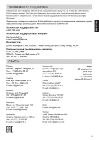
2. Install the switch into the rack.
3. Use the screws that were provided with the rack
to secure the switch to the rack.
Figure 6
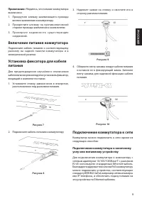
Grounding the Switch
This step must be completed before powering on
the switch.
Required tools and equipment for grounding
• Grounding screw (included) and one M4x6
(metric) pan-head screw (not included).
• Grounding cable (not included). The grounding
cable should be sized according to local and
national installation requirements. Depending
on the power supply and system, a 12 to 6 AWG
copper conductor is required for installation.
C o m m e r c i a l l y a v a i l a b l e 6 AW G w i r e i s
recommended. The length of the cable depends
on the proximit y of the switch to proper
grounding facilities.
• A screwdriver (not included).
Note:
Verify that the system is powered off.
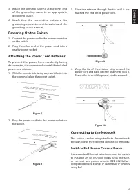
1. Remove the grounding screw from the back of
the device and place the #8 terminal lug ring of
the grounding cable on top of the grounding
screw opening.
2. Insert the grounding screw back into the screw
opening and use a screwdriver to tighten the
grounding screw.
Содержание
- 6 Правила и условия безопасной эксплуатации; технических характеристиках устройства.
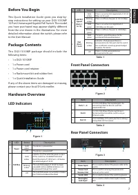
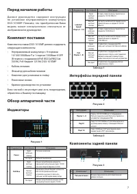
- 7 Интерфейсы передней панели; Компоненты задней панели; Перед началом работы; Индикаторы
- 8 Установка коммутатора; Установка коммутатора в стойку; Заземление коммутатора; Необходимые инструменты и оборудование
- 9 Включение питания коммутатора; Подключение коммутатора к сети; Подключение коммутатора к конечному
- 10 Подключение коммутатора к; Дополнительная
- 11 Технические характеристики; Аппаратное обеспечение; Функционал
- 12 ТЕХНИЧЕСКАЯ ПОДДЕРЖКА; официальных праздничных дней. Звонок бесплатный по всей России.; Техническая поддержка через Интернет:; Հայաստան; לארשי
Характеристики

Остались вопросы?Не нашли свой ответ в руководстве или возникли другие проблемы? Задайте свой вопрос в форме ниже с подробным описанием вашей ситуации, чтобы другие люди и специалисты смогли дать на него ответ. Если вы знаете как решить проблему другого человека, пожалуйста, подскажите ему :)


