
Измерительные приборы Defort DMM-1000N - инструкция пользователя по применению, эксплуатации и установке на русском языке. Мы надеемся, она поможет вам решить возникшие у вас вопросы при эксплуатации техники.
Если остались вопросы, задайте их в комментариях после инструкции.
"Загружаем инструкцию", означает, что нужно подождать пока файл загрузится и можно будет его читать онлайн. Некоторые инструкции очень большие и время их появления зависит от вашей скорости интернета.


11
GB
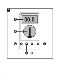
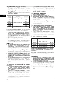
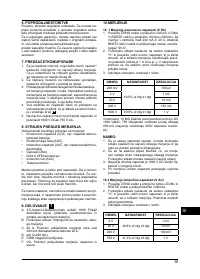
10.6 HFE-TRANSISTOR MEASUREMENT
1. Remove the measuring cable.
2. Set the switch on the hFE setting.
3. Find out whether this transistor is a NPN or PNP
transistor and connect the Emitter- (e), Basic (b)
and collector- (c) cable to the appropriate socket in
the switch gear panel on the front side.
4. The display shows the (approximate) hFE value for
a basic current of 10 [A, V CE 2.8 V.
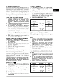
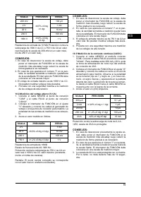
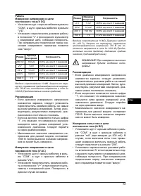
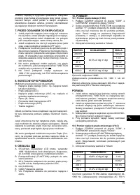
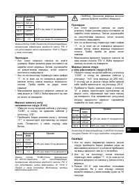
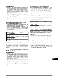
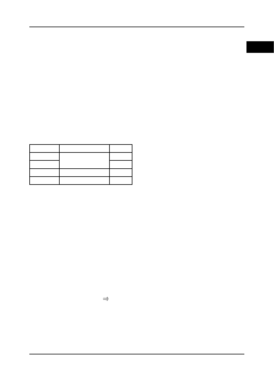
10.7 MEASURING ALTERNATING CURRENT
(AAC)
1. Connect the BLACK lead to the COM connector
socket. Connect the RED lead to the «VYmA» con-
nector socket. For measurements between 200 mA
and 20 A, remove RED lead to «20 A» connector
socket.
2. Set the FUNCTION switch on the desired «A~» set-
ting and connect the leads in series to the power
circuit to be measured. The polarity of the measur-
ing tips is not relevant.
3. Read off the value in (milli-) Ampere.
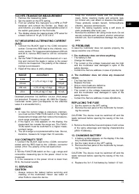
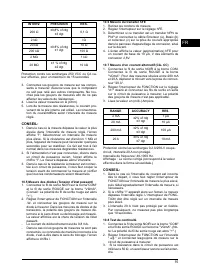
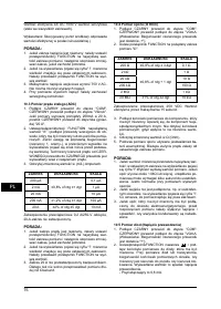
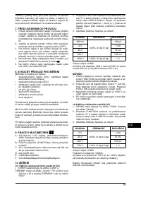
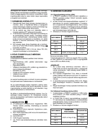
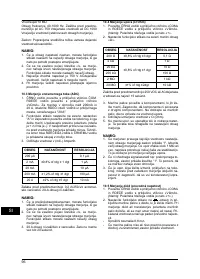
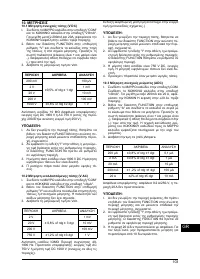
RANGE
ACCURACY
RES.
2 mA
± 1,2% of rdg ± 3 dgt
1 [A
20 mA
10 [A
200 mA
± 2% of rdg ± 3 dgt
100 [A
20 A
± 3% of rdg ± 7 dgt
10 mA
Overload protection 0.2 AI250-V cut-out, 20-A-range
not protected. Frequency range: 40-1000 Hz. Display:
Corrected centre point (corresponds to the effective
value in a sinusoidal form.)
HINT:
1. In case the current range is previously unknown,
you must set the FUNCTION switch in the highest
measurement range and then reduce the measure-
ment range gradually if required.
2. If the Q gure «I» now appears on the display, the
measurand lies outside the range set. The FUNC-
TION switch must be switched to a higher meas-
urement range.
3. The 20 A range is not protected with a fuse. Do not,
therefore, measure for longer than 10 seconds.
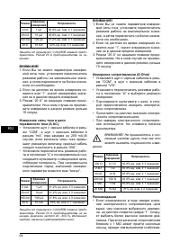
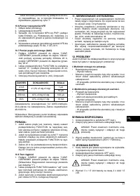
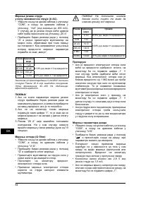
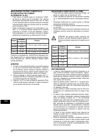
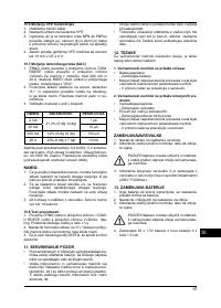
10.8 CONTINUITY TEST
1. Connect the BLACK lead to the «COM» connector
socket and the RED lead to the «VYmA» connector
socket. (Hint: The polarity of the red lead is then
«+».)
2. Set the FUNCTION switch on the «
» range and
connectthe measuring tips to the power circuit to be
measured.
3. If the resistance in the power circuit is lower than
50 Y, the buzzer sounds.
11. SERVICING
CAUTION
• Always remove the battery before servicing and
cleaning of the multimeter. Never use water or
other X uids to clean the device.
• Keep the instrument leads and the multimeter
clean. Some cleaning media and solvents (pet-
rol, thinner etc.) can attach or dissolve the plastic.
These products contain benzol, trichloroethane,
chlorine, aqueous ammonia etc.
• Clean the casing regularly using a soft piece of
cloth, preferably after every use.
•
Remove the stubborn dirt using moist cloth. Do not
use any solvents such as petrol, alcohol, ammoniac
solution etc. Such substances damage the plastic
parts.
12. PROBLEMS
In case the multimeter does not operate properly, the
cause could be one of these:
1. The multimeter does not show anything.
• The battery is X at.
- Change the battery.
• The current or the voltage measured was too high
and the multimeter was damaged in spite of the
safety devices.
- Contact the Service address in case of problems.
2. The multimeter does not show any measured
values.
• The fuse has burnt.
- Replace the fuse.
• One or more leads are defective.
- Replace the instrument leads.
• The current or the voltage measured was too high
and the multimeter was damaged in spite of the
safety devices.
- Contact the Service address in case ofproblems.
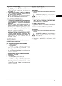
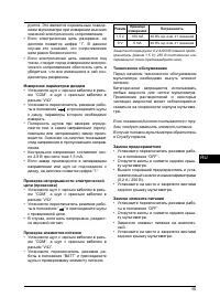
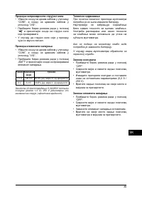
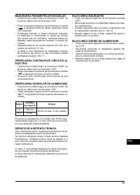
REPLACING THE FUSE
1. Set the switch on the OFF setting.
2. Remove the rear panel of the multimeter by loosen-
ing the screws.
CAUTION! The device must be switched off and the
leads removed before opening the casing of the mul-
timeter.
3. Remove the defective fuse and replace it with a fuse
of the same amperage and tripping characteristics
(250V~F200mAL).
13. CHANGING BATTERY
1. A battery symbol appears on the display if the bat-
tery is almost discharged.
2. Set the rotary knob on the OFF setting.
3. Remove the rear panel of the multimeter by loosen-
ing the screws.
CAUTION! The device must be switched off and the
leads removed before opening the casing of the mul-
timeter.
4. Replace the 3x 1,5 Volt battery by 3xAAA 1,5 Volt.
Характеристики

Остались вопросы?Не нашли свой ответ в руководстве или возникли другие проблемы? Задайте свой вопрос в форме ниже с подробным описанием вашей ситуации, чтобы другие люди и специалисты смогли дать на него ответ. Если вы знаете как решить проблему другого человека, пожалуйста, подскажите ему :)


