
Холодильник Liebherr CUesf 3503 - инструкция пользователя по применению, эксплуатации и установке на русском языке. Мы надеемся, она поможет вам решить возникшие у вас вопросы при эксплуатации техники.
Если остались вопросы, задайте их в комментариях после инструкции.
"Загружаем инструкцию", означает, что нужно подождать пока файл загрузится и можно будет его читать онлайн. Некоторые инструкции очень большие и время их появления зависит от вашей скорости интернета.
17
8 Instructions for installation and modification
The
external dimensions
of the appliance can be seen on
fig.
S.
Do not install the appliance side-by-side with another refri-
gerator or freezer. This is important to prevent condensation
and consequential damage from it.
All types and models are subject to continuous improvement
and the manufacturer therefore reserves the right to make
modifications in the shape, equipment and technology.
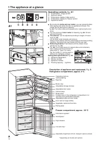
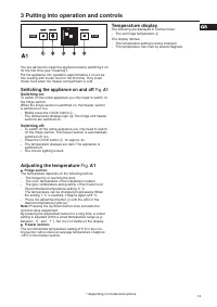
Before reading, please fold out and
refer to the illustrated back page.
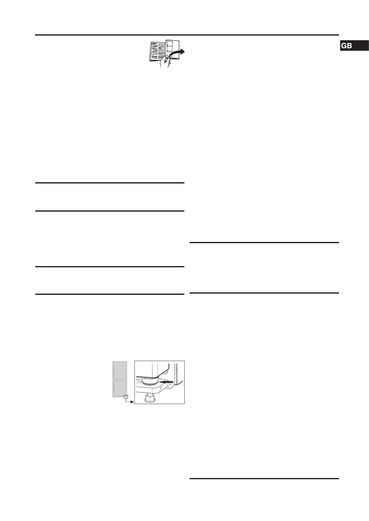
Insertion into row of kitchen units
1
top unit
2
refrigerator/freezer
3
Kitchen cupboard
4
wall
Fig.
U
: The appliances can be installed in a row of kitchen
units. To adapt the height of the appliance to the surrounding
furniture a top unit
1
can be added.
When retrofitting with standard kitchen cabinets (max. depth
580 mm), the appliance can be set up directly next to the
kitchen cupboard Fig.
U
3
. The appliance door protrudes
34 mm at the side and 50 mm in the middle of the appliance
against the front panel of the kitchen cupboard. It can
therefore be opened and closed without any problems.
Important for ventilation:
- On the rear side of the top unit there must be a ventilation duct
of at least 50 mm depth along the entire width of the top unit.
- The area of ventilation underneath the ceiling must be at
least 300 cm².
- The larger the ventilation cross section, the more energy
the appliance will be able to save.
If the appliance is installed with the hinge side against a wall
Fig.
U
4
, the distance between the appliance and the wall
must be at least 36 mm. This corresponds with the handle
protrusion when the door is open.
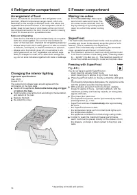
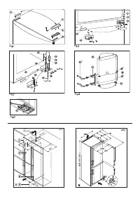
Changing over the door hinges
You can change over the door hinges if necessary.
Ensure that the following tools are to hand:
- Torx® 25
- Torx® 15
- Screwdriver
- Cordless screwdriver, if necessary
- Second person for fitting work, if needed
- Accompanying Allen key size 2
Detaching the upper door
- Close the upper door.
- Pull off the cover Fig. 1 (1) forwards and upwards.
- Lift off the cover Fig. 1 (2).
CAUTION
Risk of injury if the door tips!
- Take good hold of the door.
- Set down the door carefully.
- Unscrew the upper turn hinge Fig. 1 (3) (2x Torx® 25)
Fig. 1 (4) and lift it off.
- Lift up the upper door and set it aside.
Detaching the lower door
- Close the lower door.
- Draw the middle bearing pin Fig. 2 (11) out of the turn
hinge and lower door.
- Remove the plastic cap Fig. 2 (10).
CAUTION
Risk of injury if the door tips!
- Take good hold of the door.
- Set down the door carefully.
- Open the lower door.
- Unscrew the middle turn hinge (2x Torx® 25). Fig. 2 (13)
- Lift up the door and set it aside.
Transferring the middle bearing elements
- Carefully detach the cover panel Fig. 2 (12).
- Turn the middle turn hinge Fig. 2 (13) with the washer Fig.
2 (14) through 180° and screw it firmly into place on the
new hinge side (with 4 Nm).
- Turn the cover panel Fig. 2 (12) through 180° and snap it
into place again on the new handle side.
Transferring the lower bear-
ing elements
For appliances without
height adjustment
- Lift out the bearing pin Fig. 3
(22) together with washer
Fig. 3 (23) and foot Fig. 3 (24).
- Lift off the stopper Fig. 3 (21).
- Unscrew Fig. 3 (26) the turn hinge Fig. 3 (25).
- Unscrew Fig. 3 (29) the bearing element Fig. 3 (28), trans-
fer it to the opposite location hole of the turn hinge and
screw it firmly into place.
- Carefully lift off the cover on the handle side Fig. 3 (27)
and transfer it to the opposite side.
- Screw the turn hinge Fig. 3 (25) firmly into place on the
new hinge side, possibly using a cordless screwdriver
(with 4 Nm).
- Re-insert the stopper Fig. 3 (21) into the other hole.
- Re-insert the bearing pin Fig. 3 (22) together with washer
and foot. In so doing, pay attention that the locating lug
points backwards.
Transferring the handles
On both the upper and lower door:
- Transfer the spring clamp Fig. 5 (31): Depress the latch
nose and pull the spring clamp off over it.
- Slide the spring clamp into place on the new hinge side
until it clicks into place.
- Lift the stopper Fig. 6 (30) out of the door bearing bush
and transfer it.
- Detach door handle Fig. 6 (32), stopper Fig. 6 (33) and
pressure plates Fig. 6 (34) and transfer to the opposite side.
- When fitting the pressure plates on the opposite side,
make sure they snap properly into place*.
Fitting the lower door
- Place the lower door from above onto the lower bearing pin.
- Close the door.
- Place the plastic cap Fig. 2 (10) back onto the middle turn
hinge Fig. 2 (13).
- Place the middle bearing pin Fig. 2 (11) in the lower door, on
the new hinge side, through the middle turn hinge Fig. 2 (13).
Fitting the upper door
- Place the upper door on the middle bearing pin Fig. 2 (11).
- Insert the upper turn hinge Fig. 1 (3) in the door on the
new hinge side.
- Screw the upper turn hinge firmly into place (with 4 Nm)
(2x Torx® 25) Fig. 1 (4). Possibly make preliminary holes
with a bradawl or use a cordless screwdriver.
- Apply the cover Fig. 1 (1) and cover Fig. 1 (2) to the op-
posite side from the outside and snap them into place.
Aligning the doors
- If necessary, align the doors to the appliance housing by
way of the two oblong holes in the bottom turn hinge and
middle turn hinge Fig. 2 (13). To do so, unscrew the mid-
dle screw in the bottom turn hinge.
WARNING
Risk of injury due to the door dropping out!
If the bearing parts are not screwed into place firmly enough,
the door may drop out. This may lead to severe injuries.
What is more, the door may not close and therefore the
appliance may fail to cool properly.
- Screw the turn hinges firmly into place with 4 Nm.
- Check all of the screws and retighten if necessary.
Характеристики

Остались вопросы?Не нашли свой ответ в руководстве или возникли другие проблемы? Задайте свой вопрос в форме ниже с подробным описанием вашей ситуации, чтобы другие люди и специалисты смогли дать на него ответ. Если вы знаете как решить проблему другого человека, пожалуйста, подскажите ему :)


