
Вытяжки Turboair Gea 1M/GRFX/A/60 - инструкция пользователя по применению, эксплуатации и установке на русском языке. Мы надеемся, она поможет вам решить возникшие у вас вопросы при эксплуатации техники.
Если остались вопросы, задайте их в комментариях после инструкции.
"Загружаем инструкцию", означает, что нужно подождать пока файл загрузится и можно будет его читать онлайн. Некоторые инструкции очень большие и время их появления зависит от вашей скорости интернета.


10
Installation
The minimum distance between the supporting surface for the
cooking vessels on the hob and the lowest part of the range
hood must be not less than 60cm from electric cookers and
70cm from gas or mixed cookers.
If the instructions for installation for the gas hob specify a
greater distance, this must be adhered to.
Electrical connection
The mains power supply must correspond to the rating
indicated on the plate situated inside the hood. If provided with
a plug connect the hood to a socket in compliance with current
regulations and positioned in an accessible area. If it not fitted
with a plug (direct mains connection) or if the plug is not
located in an accessible area apply a bi-polar switch in
accordance with standards which assures the complete
disconnection of the mains under conditions relating to over-
current category III, in accordance with installation instructions.
Warning!
Before re-connecting the hood circuit to the mains
supply and checking the efficient function, always check that
the mains cable is correctly assembled.
Mounting
Before beginning installation:
•
Check that the product purchased is of a suitable size for
the chosen installation area.
• To facilitate installation, remove the fat filters and the
other parts allowed and described here, dismantle and
mount it.
To remove see also the relative paragraphs.
•
Remove the active carbon (*) filter/s if supplied (see also
relative paragraph). This/these is/are to be mounted only
if you want lo use the hood in the filtering version.
• Check (for transport reasons) that there is no other
supplied material inside the hood (e.g. packets with
screws (*), guarantees (*), etc.), eventually removing
them and keeping them.
•
If possible, disconnect and move freestanding or slide-in
range from cabinet opening to provide easier access to
rear wall/ceiling. Otherwise put a thick, protective
covering over countertop, cooktop or range to protect
from damage and debris. Select a flat surface for
assembling the unit. Cover that surface with a protective
covering and place all canopy hood parts and hardware
in it.
• Disconnect the hood during electrical connection, by
turning the home mains switch off.
•
In addition check whether near the installation area of the
hood (in the area accessible also with the hood mounted)
an electric socket is available and it is possible to
connect a fumes discharge device to the outside (only
suction version).
• Carry out all the masonry work necessary (e.g.
installation of an electric socket and/or a hole for the
passage of the discharge tube).
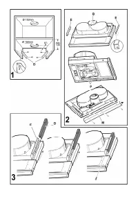
Preliminary information for installation of the hood:
Attention!
The 2 fixing brackets are lodged in the
protection in polyester packing
The brackets are one right
R
and one left
L
(see bossing
shown on the brackets).
1.
Fix
the
D
bracket (
Fig.1
) to the side panel of the wall unit
with two screws for every bracket (the right
R
bracket on
the right side and the left
L
bracket on the left side).
Align the bracket with the lower border.
Position the bracket to touch the back border of the wall
cabinet, considering that the back border of the bracket
corresponds to the back side of the cooker hood;
If the cooker hood is provided with a spacer, in case of
use, move the bracket forward to the same thickness as
the spacer.
Drill a hole on the ceiling of the wall cabinet to pass the
discharge tube and the electrical cable (the quote
indicated in
Fig. 1
does not include the eventual spacer).
2.
If not already mounted, fix the two
E
brackets (
Fig.2
) to
the sides of the hood (one per side).
a. remove the extractable part of the cooker hood;
b. remove the grease filter/s;
c. fix the brackets with two screws
P
per bracket from
inside the cooker hood, affix them as more as possible
upwards (air exit side) and then serrate the screws.
3.
Affix the spacer
M
with three Clips from the external part
of the cooker hood (if supplied -
Fig. 2
).
4.
Insert the cooker hood in the wall cabinet, ensuring to
position the cooker hood bracket
E
above the wall
cabinet bracket
D
(
Fig. 3
).
Thread the electric cable through the appropriate
perforation.
5.
Block the cooker hood with two screws on the frontal part
(
Fig. 3
– one per side).
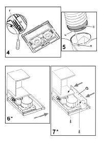
6.
Connect the cable to the electrical mains, only when the
installation is completed.
7.
If the cooker hood should not touch perfectly with the
lower border of the wall cabinet then regulate by
loosening the screws
P
of the brackets
E
mounted on the
cooker hood (
Fig. 2
), it will be possible to regulate the
perfect matching of the cooker hood and wall cabinet,
once regulated tighten the screws.
8.
Regulate the gliding of the extractable drawer in relation
to the depth of the wall cabinet by acting on the two
skirting boards
F
(
Fig. 4
).
In this way it will be possible to place the front in line with
the wall cabinet (
Fig. 4
).
a. Loosen the screws on the skirting board
F
;
b. Move the ledges backwards or forwards depending on
requirement.
c. Lock in the screws on the ledges.
9.
Install a discharge tube on the connection ring
C
supplied,
preferably with a diameter equivalent to the connection
ring (
Fig. 5
). the discharge tube should be sufficiently
long to reach outside (Suction version) or the ceiling of
the wall cabinet (Filter version).
10.
Fix the connection ring
C
(snap into place), at the upper
exit of the cooker hood.


