
Вытяжки Korting KHA 4970 X Cylinder - инструкция пользователя по применению, эксплуатации и установке на русском языке. Мы надеемся, она поможет вам решить возникшие у вас вопросы при эксплуатации техники.
Если остались вопросы, задайте их в комментариях после инструкции.
"Загружаем инструкцию", означает, что нужно подождать пока файл загрузится и можно будет его читать онлайн. Некоторые инструкции очень большие и время их появления зависит от вашей скорости интернета.


- 8 -
•
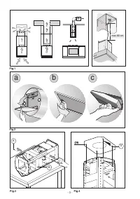
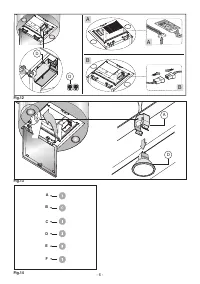
Hood assembly
Remove the structure from the packaging and remove
the 2 screws
A
to separate the upper part from the lower
par t (fig.3)
.
-
Position the drilling template on the ceiling, making sure
that the arrow is on the right-hand side in relation to the
appliance controls, as indicated in Figure 4.
Make 4, Ø8 holes in the ceiling and drive in 3 screws
without completely tightening them. Pay attention not to
inser t the screw into the hole marked with an
X
on the
hole template (the screws and expansion plugs must be
suitable for the type of wall).
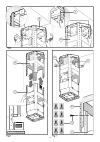
- Take the upper part of the structure
B
(fig.5) and inser t
the 3 slots onto the 3 screws that are not completely
tightened. Rotate slightly to fit (fig.5) .
Dr ive in the fourth screw
X
and tighten the remaining 3
to allow definitive blocking of the upper par t of structure
B.
-
Take the lower par t of the telescopic structure
C
and
inser t it into the upper structure
B
(fig.6).
Please note:
To avoid scratching the upper duct, first adjust its height
as desired, using the measurements given in (Fig. 6) as
a reference, and then fix it in place using the 8 screws
provided
G
(Fig. 7).
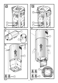
- Extractor hood:
connect the flexible hose
H
(not
supplied) to the air exhaust hole made previously and fix
the hose to the connector flange
F
(Fig. 8).
- Filter hood:
connect the flexible hose
H
(not supplied)
to the deflector
M
(Fig. 9).
- Fix the flexible hose
H
over the connector flange
F
(Fig.
9).
- The active charcoal filters must be fitted to the extraction
assembly located inside the cooker hood (Fig. 2c).
•
Before proceeding with the installation process, open
the panel by pressing on the point indicated in Fig. 2a;
this will make the cooker hood easier to handle.
Remove the aluminium panel by pulling the handle as
indicated in Fig. 2b. If the product is supplied with active
charcoal filters, remove them by pulling the lever outwards
as indicated in Fig. 2c.
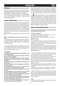
Take the ducts out of the packaging (Fig. 10A) and se-
parate the upper duct
Y
from the lower duct
L
.
Remove the protective materials from the upper duct
Y
,
as indicated in figure 10A.
- Take the upper duct
Y
and fix it to the str ucture using
the 2 screws
X
(Fig. 10B).
Join the lower par t of the cooker hood
L
to the upper
duct
Y
until it clicks into place, then secure it in this
position on the lower par t of the cooker hood using the 4
screws
A
as indicated in figure 11.
- Electrical connection
Before perfor ming this connection, loosen the 4 screws
D
on the two boxes and open the cover panels (Fig. 12).
- Perfor m the necessary electrical connections between
the cooker hood body and the motor assembly (Fig. 12
A and B).
USE AND MAINTENANCE
•
We recommend that the cooker hood is switched on
before any food is cooked. We also recommend that the
appliance is left running for 15 minutes after the food is
cooked, in order to thoroughly eliminate all contaminated
air.
The effective perfor mance of the cooker hood depends
on constant maintenance; the anti-grease filter and the
active carbon filter both require special attention.
• The anti-grease filter is used to trap any grease par ticles
suspended in the air, therefore is subject to saturation
(the time it takes for the filter to become saturated
depends on the way in which the appliance is used).
The acrylic filter, which is found resting on the grille,
should be replaced when the text, visible through the
grille, changes colour and the ink spreads; the new filter
should be fitted in such a way that the text can be seen
through the grille from outside the cooker hood.
If the filters do not have any text on them, or if metal
filters or aluminium panel filters are used, they should
be washed every 2 months in order to prevent the risk of
fire. To wash the filters, proceed as follows:
- Remove the filter from the grille and wash it using a
solution of water and neutral liquid detergent, leaving
the dir t to soften.
- Rinse thoroughly with war m water and leave to dry.
T h e m e t a l f i l t e r s a n d / o r a l u m i n i u m p a n e l a r e a l s o
dishwasher safe. If the filters are made using aluminium,
or if an aluminium panel is used, after a few washes the
colour may change. This does not mean they have to be
replaced.
If the replacement and washing instructions are not
followed, the anti-grease filters may present a fire hazard.
• The active carbon filters are used to purify the air which
i s r e l e a s e d b a ck i n t o t h e r o o m . T h e f i l t e r s a r e n o t
washable or re-usable and must be replaced at least once
every four months. The active carbon filter saturation level
depends on the frequency with which the appliance is
used, the type of cooking performed and the regularity
with which the anti-grease filters are cleaned.
•
Remove build-up from the fan and other surfaces of
the cooker hood regularly using a cloth moistened with
d e n a t u r e d a l c o h o l o r n o n - a b ra s i ve n e u t r a l l i q u i d
detergent.
• The light on the cooker hood is designed for use during
cooking and not for general room illumination. Extended
use of the light reduces the average duration of the bulb.
• Replacing halogen light bulbs (Fig. 13).
To replace the halogen lamps
B
, from the inside of the
cooker hood press downwards with two fingers as shown
in Fig. 13.
Replace the bulbs with new ones of the same type.
• COMMANDS:
(Fig.14)
LUMINOUS
the key symbols are explained
below:
A
= LIGHT
B
= OFF
C
= SPEED I
D
= SPEED II
E
= SPEED III
F
= AUTOMATIC STOP TIMER - 15 minutes
(*)
•
If your appliance does not have the
INTENSIVE
speed
function, press key E for two seconds and it will be
activated for 10 minutes after which it will return to the
previously set speed. When the function is active the LED
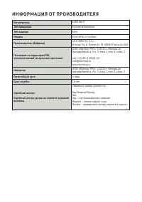
Характеристики

Остались вопросы?Не нашли свой ответ в руководстве или возникли другие проблемы? Задайте свой вопрос в форме ниже с подробным описанием вашей ситуации, чтобы другие люди и специалисты смогли дать на него ответ. Если вы знаете как решить проблему другого человека, пожалуйста, подскажите ему :)


