
Вытяжки Elica STONE IX/A - инструкция пользователя по применению, эксплуатации и установке на русском языке. Мы надеемся, она поможет вам решить возникшие у вас вопросы при эксплуатации техники.
Если остались вопросы, задайте их в комментариях после инструкции.
"Загружаем инструкцию", означает, что нужно подождать пока файл загрузится и можно будет его читать онлайн. Некоторые инструкции очень большие и время их появления зависит от вашей скорости интернета.


11
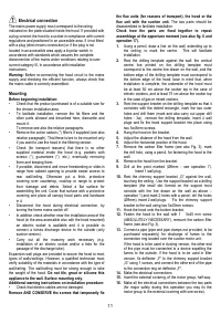
Electrical connection
The mains power supply must correspond to the rating
indicated on the plate situated inside the hood. If provided with
a plug connect the hood to a socket in compliance with current
regulations and positioned in an accessible area. If it not fitted
with a plug (direct mains connection) or if the plug is not
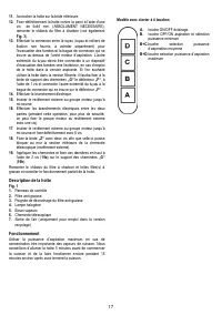
located in an accessible area apply a bi-polar switch in
accordance with standards which assures the complete
disconnection of the mains under conditions relating to over-
current category III, in accordance with installation
instructions.
Warning:
Before re-connecting the hood circuit to the mains
supply and checking the efficient function, always check that
the mains cable is correctly assembled.
Mounting
Before beginning installation:
•
Check that the product purchased is of a suitable size for
the chosen installation area.
•
To facilitate installation, remove the fat filters and the
other parts allowed and described here, dismantle and
mount it.
To remove see also the relative paragraphs.
•
Remove the active carbon (*) filter/s if supplied (see also
relative paragraph). This/these is/are to be mounted only
if you want lo use the hood in the filtering version.
•
Check (for transport reasons) that there is no other
supplied material inside the hood (e.g. packets with
screws (*), guarantees (*), etc.), eventually removing
them and keeping them.
•
If possible, disconnect and move freestanding or slide-in
range from cabinet opening to provide easier access to
rear wall/ceiling. Otherwise put a thick, protective
covering over countertop, cooktop or range to protect
from damage and debris. Select a flat surface for
assembling the unit. Cover that surface with a protective
covering and place all canopy hood parts and hardware
in it.
•
Disconnect the hood during electrical connection, by
turning the home mains switch off.
•
In addition check whether near the installation area of the
hood (in the area accessible also with the hood mounted)
an electric socket is available and it is possible to
connect a fumes discharge device to the outside (only
suction version).
•
Carry out all the masonry work necessary (e.g.
installation of an electric socket and/or a hole for the
passage of the discharge tube).
Expansion wall plugs are provided to secure the hood to most
types of walls/ceilings. However, a qualified technician must
verify suitability of the materials in accordance with the type of
wall/ceiling. The wall/ceiling must be strong enough to take
the weight of the hood.
Do not tile, grout or silicone this
appliance to the wall. Surface mounting only.
Additional warning instructions on installation procedure:
•
Check that electric cables are not damaged.
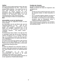
Remove AND CONSERVE the screws that temporarily fix
the flue units (for reasons of transport), the hood or the
flue unit with the suction unit.
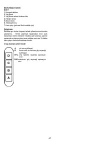
The two parts should be
disassembled to facilitate installation.
Check how the parts are fixed together to repeat
assemblage at the opportune moment (see also fig. 6 and
operation 17).
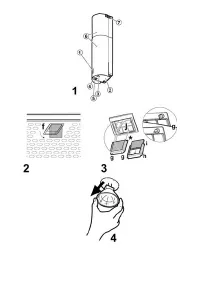
1.
Using a pencil, draw a line on the wall, extending up to
the ceiling, to mark the centre. This will facilitate
installation.
2.
Rest the drilling template against the wall: the vertical
centre line printed on the drilling template must
correspond to the centre line drawn on the wall, and the
bottom edge of the drilling template must correspond to
the bottom edge of the hood: bear in mind that, when
installation is complete, the underside of the hood must
be at least 50 cm above the cooker top in the case of
electric cookers, and at least 75 cm above the cooker top
in the case of gas or mixed cookers.
3.
Rest the support bracket on the drilling template so that it
coincides with the dotted rectangle, mark the two outer
holes and drill them (mark and also carry out upper drill
holes - 3a), remove the drilling template, insert 4 wall
plugs and fix the hood support bracket into place using
two 5x45mm screws.
4.
Hang the hood on the bracket.
5.
Adjust the distance of the hood from the wall.
6.
Adjust the horizontal position of the hood.
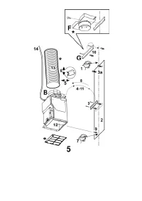
7.
Remove the carbon filter frame (see also Fig. 3); mark
the drill hole, using a pencil, for fastening the hood to the
wall.
8.
Remove the hood from the bracket.
9.
Drill at the point marked (Ø8mm - see operation 7).
Insert 1 wall plug.
10.
Rest the chimney support bracket „G“ against the wall,
touching the ceiling. Use the support bracket as a drilling
template (the small slot formed on the support must
coincide with the line drawn on the wall as above –
operation 1) and mark 2 holes with a pencil, dril the holes
(Ø8mm), insert 2 wall plugs. Fix the chimney support
bracket to the wall using two 5x45mm screws.
11.
Hook the hood onto the bottom bracket.
12.
Fasten the hood to the wall with 1 5x45 mm screw
(ABSOLUTELY NECESSARY), remount the carbon filter
frame (see also Fig. 3).
13.
Connect a pipe (pipe and pipe clamps not provided, to be
purchased separately) for discharge of fumes to the
connection ring located over the suction motor unit.
If the hood is to be used in ducting version, the other end
of the pipe must be connected to a device expelling the
fumes to the outside. If the hood is to be used in filter
version, fix deflector „F“ to the chimney support bracket
„G“ using 1 screws, and connect the other end of the pipe
to the connection ring on deflector „F“.
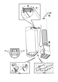
14.
Make the electrical connections.
15.
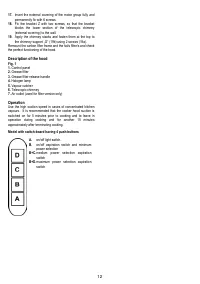
Insert the external covering, of the motor group, half-way.
16.
Make all the electrical connections between the two parts
(for major safety during this operation you may fix the
motor group to the external covering with one screw).
Характеристики

Остались вопросы?Не нашли свой ответ в руководстве или возникли другие проблемы? Задайте свой вопрос в форме ниже с подробным описанием вашей ситуации, чтобы другие люди и специалисты смогли дать на него ответ. Если вы знаете как решить проблему другого человека, пожалуйста, подскажите ему :)


