
Шлифмашины Makita GA029GZ - инструкция пользователя по применению, эксплуатации и установке на русском языке. Мы надеемся, она поможет вам решить возникшие у вас вопросы при эксплуатации техники.
Если остались вопросы, задайте их в комментариях после инструкции.
"Загружаем инструкцию", означает, что нужно подождать пока файл загрузится и можно будет его читать онлайн. Некоторые инструкции очень большие и время их появления зависит от вашей скорости интернета.


16 ENGLISH
►
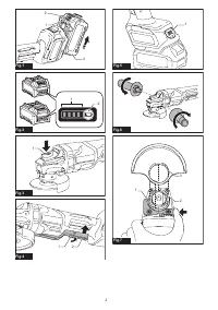
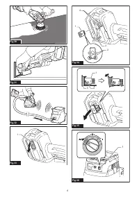
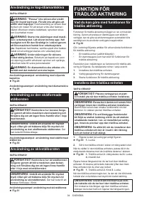
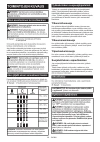
Fig.4:
1.
Lock-off lever
2.
Switch lever
To prevent the switch lever from being accidentally
pulled, a lock-off lever is provided.
To start the tool, pull the lock-off lever toward the opera
-
tor and then pull the switch lever.
To stop the tool, release the switch lever.
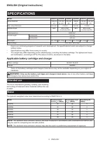
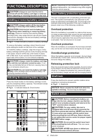
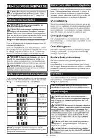
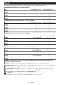
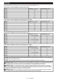
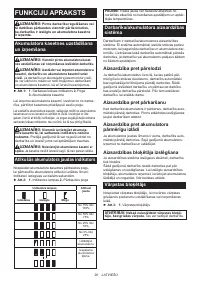
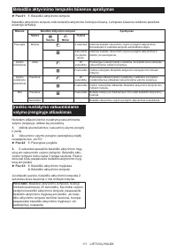
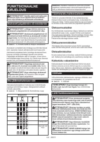
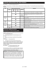
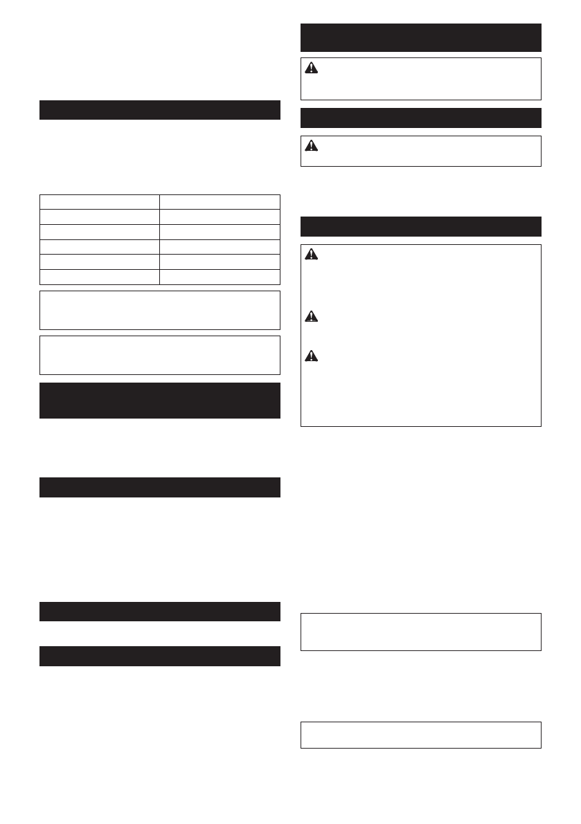
Speed adjusting dial
The rotation speed of the tool can be changed by turn
-
ing the speed adjusting dial. The table below shows
the number on the dial and the corresponding rotation
speed.
►
Fig.5:
1.
Speed adjusting dial
Number
Speed
1
3,000 min
-1
2
4,500 min
-1
3
6,000 min
-1
4
7,500 min
-1
5
8,500 min
-1
NOTICE:
If the tool is operated continuously at
low speed for a long time, the motor will get over-
loaded, resulting in tool malfunction.
NOTICE:
When changing the speed dial from "5"
to "1", turn the dial counterclockwise. Do not turn
the dial clockwise forcibly.
Accidental re-start preventive
function
When installing the battery cartridge while pulling the
switch lever, the tool does not start.
To start the tool, first release the switch lever. Then pull
the lock-off lever, and pull the switch lever.
Electronic torque control function
The tool electronically detects situations where the
wheel or accessory may be at risk to be bound. In the
situation, the tool is automatically shut off to prevent
further rotation of the spindle (it does not prevent
kickback).
To restart the tool, switch off the tool first, remove the
cause of sudden drop in the rotation speed, and then
turn the tool on.
Soft start feature
Soft start feature reduces starting reaction.
Electric brake
Only for model GA027G / GA028G / GA029G
Electric brake is activated after the tool is switched off.
The brake does not work when the power supply is shut
down, such as the battery is removed accidentally, with
the switch still on.
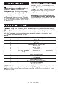
ASSEMBLY
CAUTION:
Always be sure that the tool is
switched off and the battery cartridge is removed
before adjusting or checking function on the tool.
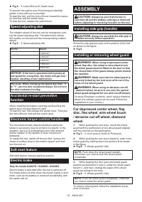
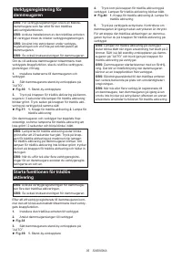
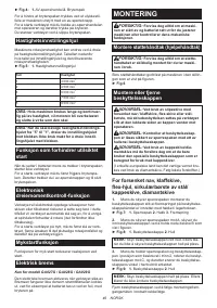
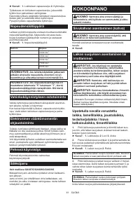
Installing side grip (handle)
CAUTION:
Always be sure that the side grip is
installed securely before operation.
Screw the side grip securely on the position of the tool
as shown in the figure.
►
Fig.6
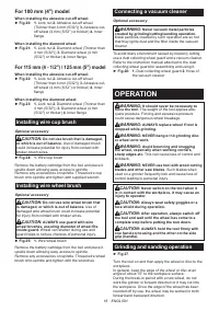
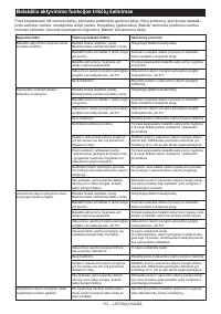
Installing or removing wheel guard
WARNING:
When using a depressed center
wheel, flap disc, flex wheel or wire wheel brush,
the wheel guard must be fitted on the tool so that
the closed side of the guard always points toward
the operator.
WARNING:
Make sure that the wheel guard is
securely locked by the lock lever with one of the
holes on the wheel guard.
WARNING:
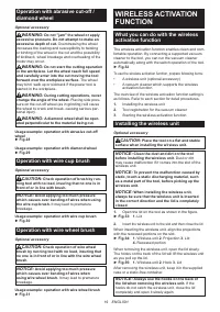
When using an abrasive cut-off
/ diamond wheel, be sure to use only the special
wheel guard designed for use with cut-off wheels.
(In some European countries, when using a diamond
wheel, the ordinary guard can be used. Follow the
regulations in your country.)
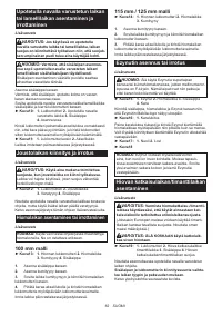
For depressed center wheel, flap
disc, flex wheel, wire wheel brush
/ abrasive cut-off wheel, diamond
wheel
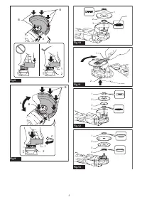
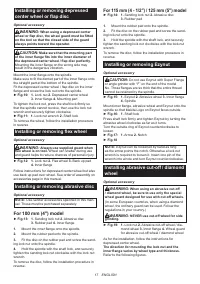
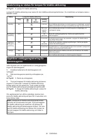
1.
While pushing the lock lever, mount the wheel
guard with the protrusions on the wheel guard aligned
with the notches on the bearing box.
►
Fig.7:
1.
Lock lever
2.
Notch
3.
Protrusion
2.
While pushing the lock lever toward A, push in the
wheel guard by holding down the portions B as shown
in the figure.
►
Fig.8:
1.
Wheel guard
2.
Hole
NOTE:
Push down the wheel guard straight.
Otherwise, you cannot push the wheel guard
completely.
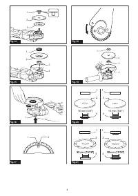
3.
While keeping the lock lever and wheel guard
position as described in step 2, rotate the wheel guard
toward C, and then, change the angle of the wheel
guard according to the work.
►
Fig.9:
1.
Wheel guard
2.
Hole
NOTE:
Push the wheel guard completely. Otherwise,
you cannot rotate the wheel guard.
To remove wheel guard, follow the installation proce-
dure in reverse.
Содержание
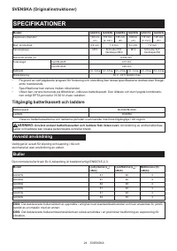
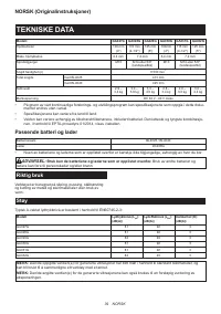
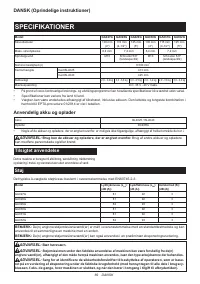
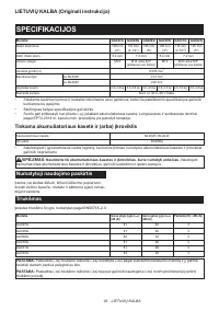
- 129 ТЕХНИЧЕСКИЕ ХАРАКТЕРИСТИКИ; Подходящий блок аккумулятора и зарядное устройство; Шум
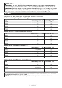
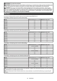
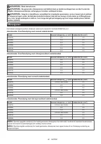
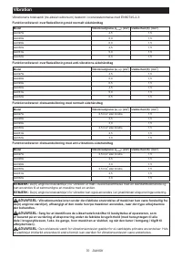
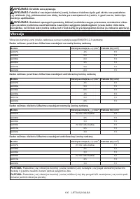
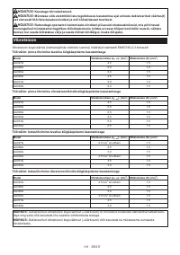
- 130 Вибрация
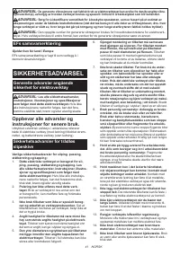
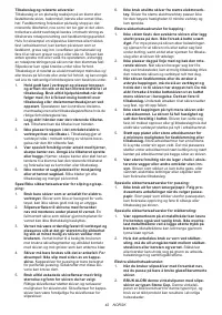
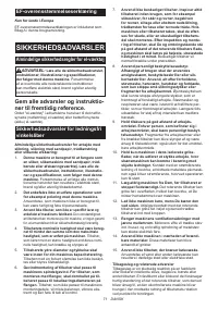
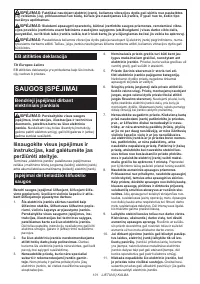
- 131 МЕРЫ БЕЗОПАСНОСТИ; Сохраните брошюру с инструк
- 134 Важные правила техники; СОХРАНИТЕ ДАННЫЕ
- 136 ОПИСАНИЕ РАБОТЫ; Защита от перегрузки
- 137 СБОРКА
- 139 Установка или снятие гайки Ezynut; Установка абразивного отрезного/; Установка чашечной проволочной
- 140 Установка дисковой проволочной щетки; Подключение пылесоса; ЭКСПЛУАТАЦИЯ; Шлифовка и зачистка
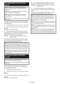
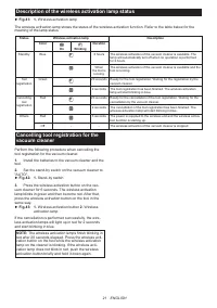
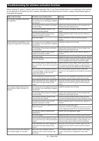
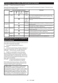
- 141 ФУНКЦИЯ БЕСПРОВОДНОЙ
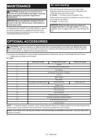
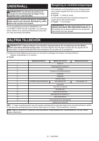
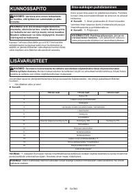
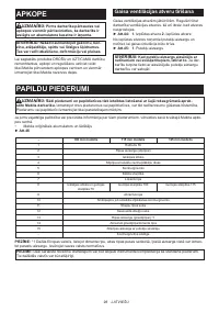
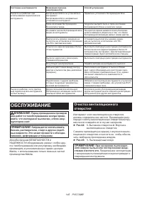
- 145 ОБСЛУЖИВАНИЕ; Очистка вентиляционного
- 146 ДОПОЛНИТЕЛЬНЫЕ ПРИНАДЛЕЖНОСТИ
Характеристики

Остались вопросы?Не нашли свой ответ в руководстве или возникли другие проблемы? Задайте свой вопрос в форме ниже с подробным описанием вашей ситуации, чтобы другие люди и специалисты смогли дать на него ответ. Если вы знаете как решить проблему другого человека, пожалуйста, подскажите ему :)


