
Пилы дисковые Makita HS004GZ - инструкция пользователя по применению, эксплуатации и установке на русском языке. Мы надеемся, она поможет вам решить возникшие у вас вопросы при эксплуатации техники.
Если остались вопросы, задайте их в комментариях после инструкции.
"Загружаем инструкцию", означает, что нужно подождать пока файл загрузится и можно будет его читать онлайн. Некоторые инструкции очень большие и время их появления зависит от вашей скорости интернета.


15 ENGLISH
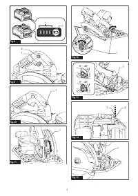
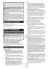
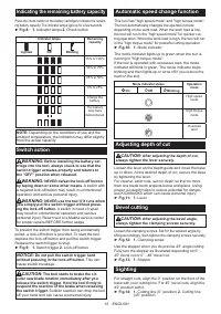
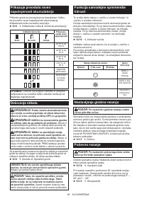
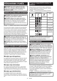
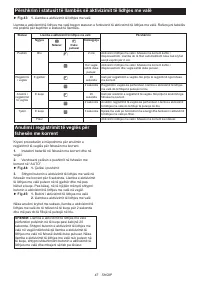
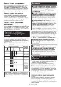
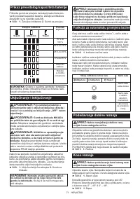
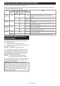
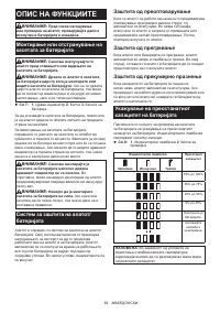
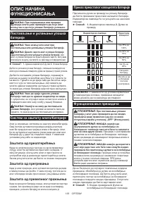
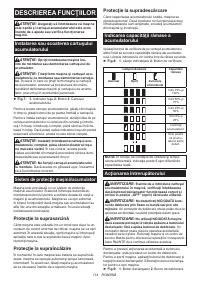
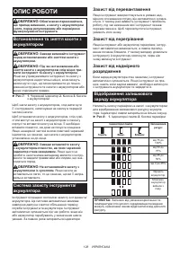
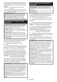
Indicating the remaining battery capacity
Press the check button on the battery cartridge to indicate the remain
-
ing battery capacity. The indicator lamps light up for a few seconds.
►
Fig.8:
1.
Indicator lamps
2.
Check button
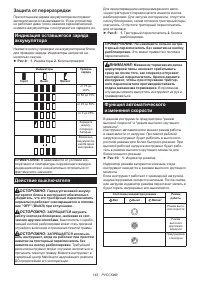
Indicator lamps
Remaining
capacity
Lighted
Off
Blinking
75% to 100%
50% to 75%
25% to 50%
0% to 25%
Charge the
battery.
The battery
may have
malfunctioned.
NOTE:
Depending on the conditions of use and the
ambient temperature, the indication may differ slightly
from the actual capacity.
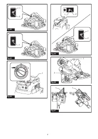
Switch action
WARNING:
Before installing the battery car
-
tridge into the tool, always check to see that the
switch trigger actuates properly and returns to
the "OFF" position when released.
WARNING:
NEVER defeat the lock-off button
by taping down or some other means.
A switch with
a negated lock-off button may result in unintentional
operation and serious personal injury.
WARNING:
NEVER use the tool if it runs when
you simply pull the switch trigger without press
-
ing the lock-off button.
A switch in need of repair
may result in unintentional operation and serious
personal injury. Return tool to a Makita service center
for proper repairs BEFORE further usage.
To prevent the switch trigger from being accidentally
pulled, a lock-off button is provided. To start the tool,
depress the lock-off button and pull the switch trigger.
Release the switch trigger to stop.
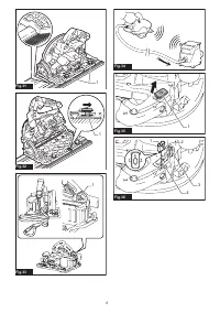
►
Fig.9:
1.
Switch trigger
2.
Lock-off button
NOTICE:
Do not pull the switch trigger hard
without pressing in the lock-off button.
This can
cause switch breakage.
CAUTION:
The tool starts to brake the cir
-
cular saw blade rotation immediately after you
release the switch trigger. Hold the tool firmly to
respond the reaction of the brake when releasing
the switch trigger.
Sudden reaction can drop the tool
off your hand and can cause a personal injury.
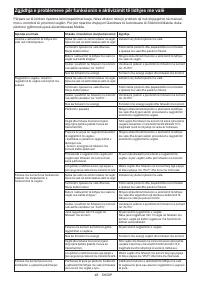
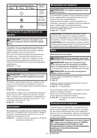
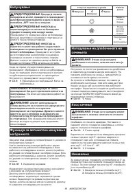
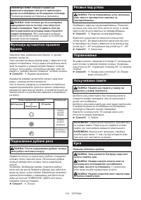
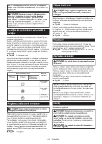
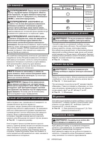
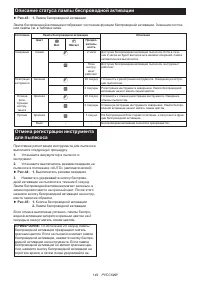
Automatic speed change function
This tool has "high speed mode" and "high torque mode".
The tool automatically changes the operation mode
depending on the work load. When the work load is low,
the tool will run in the "high speed mode" for quicker cut-
ting operation. When the work load is high, the tool will run
in the "high torque mode" for powerful cutting operation.
►
Fig.10:
1.
Mode indicator
The mode indicator lights up in green when the tool is
running in "high torque mode".
If the tool is operated with excessive load, the mode
indicator will blink in green. The mode indicator stops
blinking and then lights up or turns off if you reduce the
load on the tool.
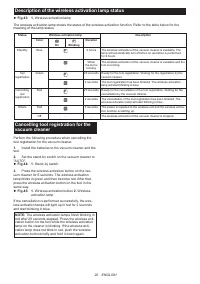
Mode indicator status
Operation
mode
On
Off
Blinking
High speed
mode
High torque
mode
Overload
alert
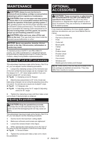
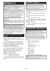
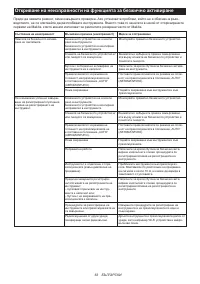
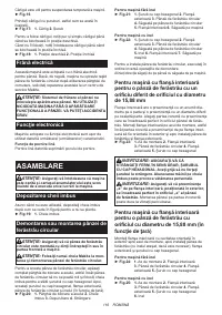
Adjusting depth of cut
CAUTION:
After adjusting the depth of cut,
always tighten the lever securely.
Loosen the lever on the depth guide and move the base
up or down. At the desired depth of cut, secure the base
by tightening the lever.
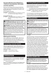
For cleaner, safer cuts, set cut depth so that no more
than one blade tooth projects below workpiece. Using
proper cut depth helps to reduce potential for danger-
ous KICKBACKS which can cause personal injury.
►
Fig.11:
1.
Lever
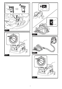
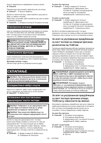
Bevel cutting
CAUTION:
After adjusting the bevel angle,
always tighten the clamping screws securely.
Loosen the clamping screws. Set for the desired angle by
tilting accordingly, then tighten the clamping screws securely.
►
Fig.12:
1.
Clamping screw
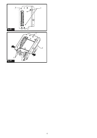
Use the stopper when you do precise 45° angle cutting.
Fully turn the stopper as illustrated depending on 0° -
45° bevel cut or 0° - 48° bevel cut.
►
Fig.13:
1.
Stopper
Sighting
For straight cuts, align the 0° position on the front of the
base with your cutting line. For 45° bevel cuts, align the
45° position with it.
►
Fig.14:
1.
Cutting line (0° position)
2.
Cutting line
(45° position)
Содержание
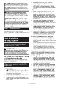
- 138 МЕРЫ БЕЗОПАСНОСТИ; Сохраните брошюру с инструк
- 140 СОХРАНИТЕ ДАННЫЕ; Важные правила техники
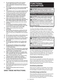
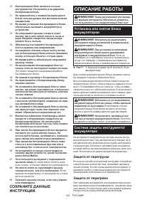
- 142 ОПИСАНИЕ РАБОТЫ; Установка или снятие блока
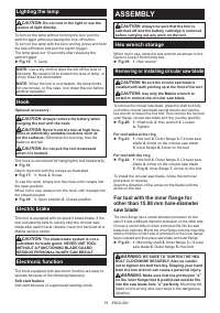
- 144 СБОРКА
- 145 ЭКСПЛУАТАЦИЯ
- 147 Что позволяет делать функция
- 148 Регистрация инструмента для
- 151 ОБСЛУЖИВАНИЕ; Регулировка точности резки под
- 152 Регулировка параллельности; ДОПОЛНИТЕЛЬНЫЕ
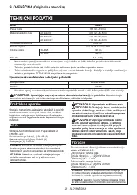
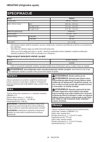
Характеристики

Остались вопросы?Не нашли свой ответ в руководстве или возникли другие проблемы? Задайте свой вопрос в форме ниже с подробным описанием вашей ситуации, чтобы другие люди и специалисты смогли дать на него ответ. Если вы знаете как решить проблему другого человека, пожалуйста, подскажите ему :)


