
Пилы дисковые Bosch 0.601.675.000 - инструкция пользователя по применению, эксплуатации и установке на русском языке. Мы надеемся, она поможет вам решить возникшие у вас вопросы при эксплуатации техники.
Если остались вопросы, задайте их в комментариях после инструкции.
"Загружаем инструкцию", означает, что нужно подождать пока файл загрузится и можно будет его читать онлайн. Некоторые инструкции очень большие и время их появления зависит от вашей скорости интернета.


16
| English
1 609 929 Y20 | (13.7.11)
Bosch Power Tools
32
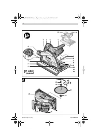
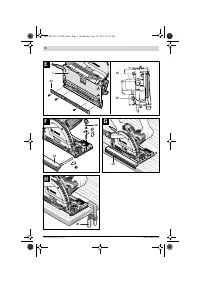
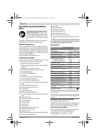
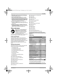
Cutting mark, 0 °
33
Cutting mark, 45 °
34
Plastic insert for base plate
35
Knurled screws for play adjustment of guide groove
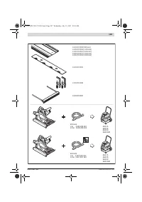
* Accessories shown or described are not part of the standard de-
livery scope of the product. A complete overview of accessories
can be found in our accessories program.
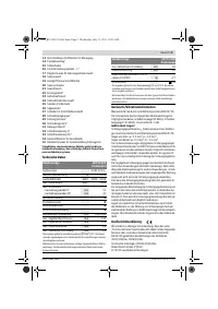
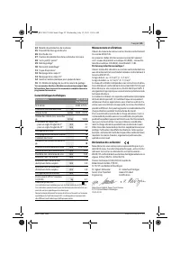
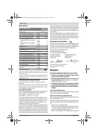
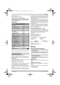
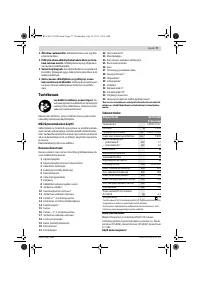
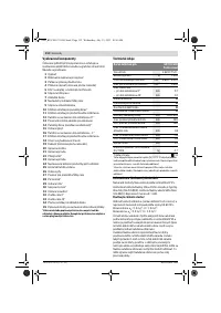
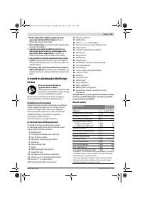
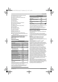
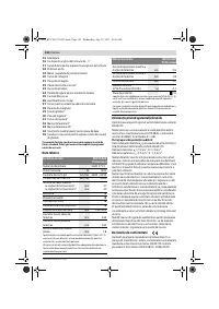
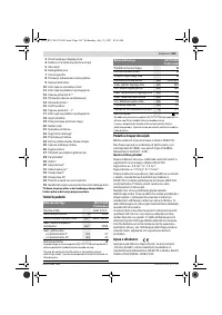
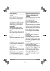
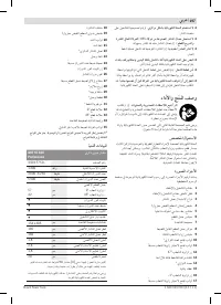
Technical Data
Noise/Vibration Information
Measured sound values determined according to EN 60745.
Typically the A-weighted noise levels of the product are:
Sound pressure level 92 dB(A); Sound power level
103 dB(A). Uncertainty K = 3 dB.
Wear hearing protection!
Vibration total values a
h
(triax vector sum) and uncertainty K
determined according to EN 60745:
Cutting wood: a
h
<2.5 m/s
2
, K = 1.5 m/s
2
,
Cutting metal: a
h
<2.5 m/s
2
, K = 1.5 m/s
2
.
The vibration emission level given in this information sheet
has been measured in accordance with a standardised test
given in EN 60745 and may be used to compare one tool with
another. It may be used for a preliminary assessment of expo-
sure.
The declared vibration emission level represents the main ap-
plications of the tool. However if the tool is used for different
applications, with different accessories or poorly maintained,
the vibration emission may differ. This may significantly in-
crease the exposure level over the total working period.
An estimation of the level of exposure to vibration should also
take into account the times when the tool is switched off or
when it is running but not actually doing the job. This may sig-
nificantly reduce the exposure level over the total working pe-
riod.
Identify additional safety measures to protect the operator
from the effects of vibration such as: maintain the tool and the
accessories, keep the hands warm, organisation of work pat-
terns.
Declaration of Conformity
We declare under our sole responsibility that the product de-
scribed under “Technical Data” is in conformity with the fol-
lowing standards or standardization documents: EN 60745
according to the provisions of the directives 2004/108/EC,
2006/42/EC.
Technical file (2006/42/EC) at:
Robert Bosch GmbH, PT/ESC,
D-70745 Leinfelden-Echterdingen
Robert Bosch GmbH, Power Tools Division
D-70745 Leinfelden-Echterdingen
25.05.2011
Assembly
Mounting/Replacing the Saw Blade
f
Before any work on the machine itself, pull the mains
plug.
f
When mounting the saw blade, wear protective gloves.
Danger of injury when touching the saw blade.
f
Only use saw blades that correspond with the charac-
teristic data given in the operating instructions.
f
Do not under any circumstances use grinding discs as
the cutting tool.
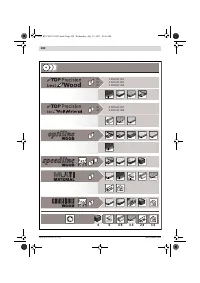
Selecting a Saw Blade
An overview of recommended saw blades can be found at the
end of this manual.
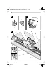
Removal of the Saw Blade (see figure A)
Adjust the maximal cutting depth, see section “Adjusting the
Cutting Depth”.
For changing the cutting tool, it is best to place the machine
on the face side of the motor housing.
– Pivot lever
3
toward the front.
– Push lock-off button
2
toward the front and press the saw
toward base plate
7
until it engages in the position for
changing the saw blade.
– Press the spindle lock button
25
and keep it pressed.
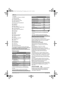
Circular Saw
GKT 55 GCE
Professional
Article number
3 601 F75 0..
Rated power input
W
1 400
No-load speed
min
-1
3 600 – 6 250
Rotational speed under load, max.
min
-1
5 900
Cutting depth, max.
– for 0 ° bevel angle
– for 45 ° bevel angle
mm
mm
57
42
Spindle lock
z
Speed preselection
z
Constant electronic control
z
Reduced starting current
z
Base plate dimensions
mm
154 x 305
Saw blade diameter, max.
mm
165
Saw blade diameter, min.
mm
160
Blade thickness, max.
mm
1.8
Tooth thickness/setting, max.
mm
2.6
Tooth thickness/setting, min.
mm
1.8
Mounting bore
mm
20
Weight according to
EPTA-Procedure 01/2003
kg
4.7
Protection class
/
II
The values given are valid for a nominal voltage [U] of 230 V. For differ-
ent voltages and models for specific countries, these values can vary.
Please observe the article number on the type plate of your machine.
The trade names of the individual machines may vary.
Dr. Egbert Schneider
Senior Vice President
Engineering
Dr. Eckerhard Strötgen
Head of Product
Certification
OBJ_BUCH-1471-001.book Page 16 Wednesday, July 13, 2011 10:56 AM
Характеристики

Остались вопросы?Не нашли свой ответ в руководстве или возникли другие проблемы? Задайте свой вопрос в форме ниже с подробным описанием вашей ситуации, чтобы другие люди и специалисты смогли дать на него ответ. Если вы знаете как решить проблему другого человека, пожалуйста, подскажите ему :)


