Памяти и накопители Seagate (ST8000VN004) - инструкция пользователя по применению, эксплуатации и установке на русском языке. Мы надеемся, она поможет вам решить возникшие у вас вопросы при эксплуатации техники.
Если остались вопросы, задайте их в комментариях после инструкции.
"Загружаем инструкцию", означает, что нужно подождать пока файл загрузится и можно будет его читать онлайн. Некоторые инструкции очень большие и время их появления зависит от вашей скорости интернета.


Seagate IronWolf SATA Product Manual, Rev. B
24
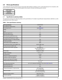
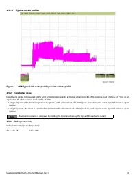
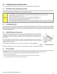
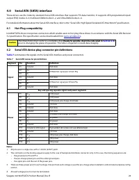
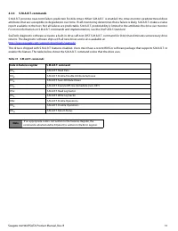
4.0
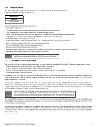
Serial ATA (SATA) interface
These drives use the industry-standard Serial ATA interface that supports FIS data transfers. It supports ATA programmed input/
output (PIO) modes 0–4; multiword DMA modes 0–2, and Ultra DMA modes 0–6.
For detailed information about the Serial ATA interface, refer to the “Serial ATA: High Speed Serialized AT Attachment” specification.
4.1
Hot-Plug compatibility
IronWolf SATA drives incorporate connectors which enable users to hot plug these drives in accordance with the Serial ATA Revision
3.2 specification. This specification can be downloaded from
.
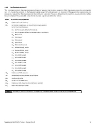
4.2
Serial ATA device plug connector pin definitions
summarizes the signals on the Serial ATA interface and power connectors.
Notes:
1.
All pins are in a single row, with a 1.27mm (0.050”) pitch.
2.
The comments on the mating sequence apply to the case of backplane blindmate connector only. In this case, the mating sequences are:
•
the ground pins P4 and P12.
•
the pre-charge power pins and the other ground pins.
•
the signal pins and the rest of the power pins.
3.
There are three power pins for each voltage. One pin from each voltage is used for pre-charge when installed in a blind-mate backplane config-
uration.
4.
All used voltage pins ( V
x
) must be terminated.
Caution
The drive motor must come to a complete stop
(Ready to spindle stop time indicated in
)
prior to changing the plane of operation. This time is required to insure data integrity.
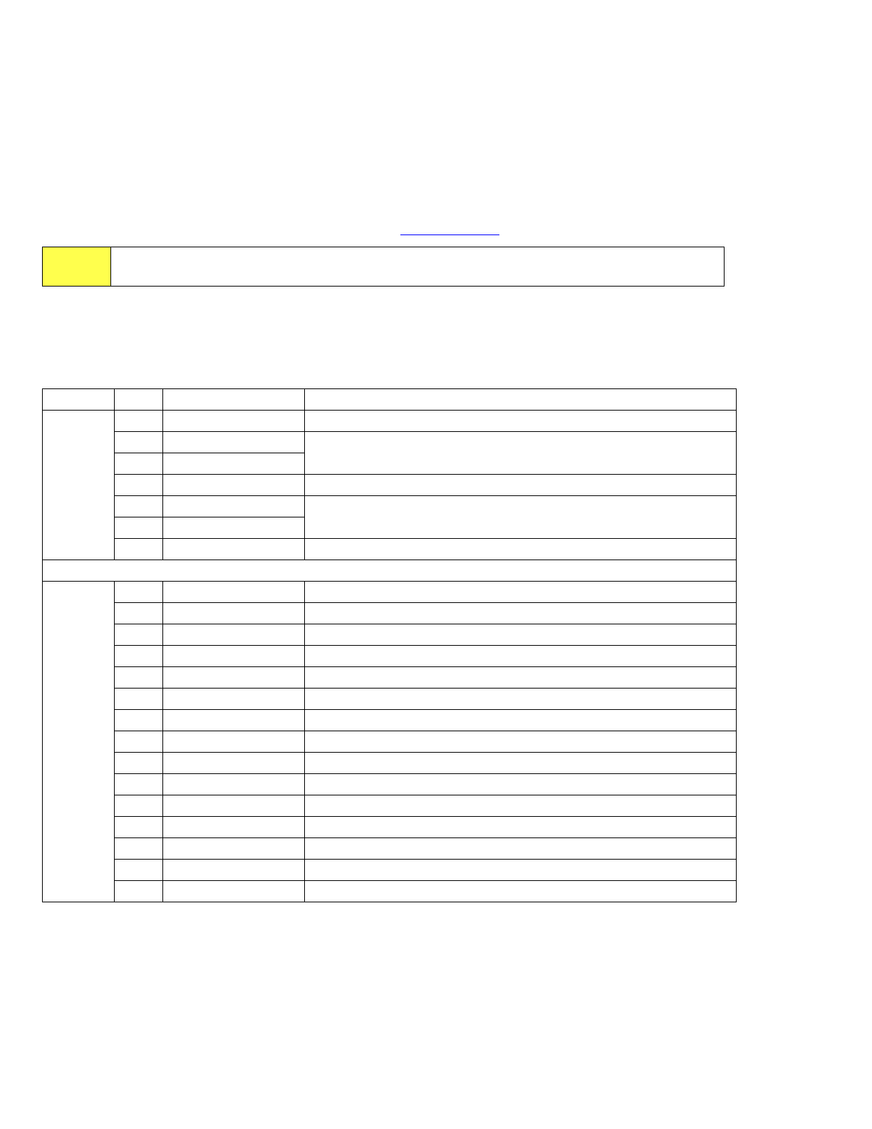
Table 7
Serial ATA connector pin definitions
Segment
Pin
Function
Definition
Signal
S1
Ground
2nd mate
S2
A+
Differential signal pair A from Phy
S3
A-
S4
Ground
2nd mate
S5
B-
Differential signal pair B from Phy
S6
B+
S7
Ground
2nd mate
Key and spacing separate signal and power segments
Power
P1
V
33
3.3V power
P2
V
33
3.3V power
P3
V
33
3.3V power, pre-charge, 2nd mate
P4
Ground
1st mate
P5
Ground
2nd mate
P6
Ground
2nd mate
P7
V
5
5V power, pre-charge, 2nd mate
P8
V
5
5V power
P9
V
5
5V power
P10
Ground
2nd mate
P11
Ground or LED signal
If grounded, drive does not use deferred spin
P12
Ground
1st mate.
P13
V
12
12V power, pre-charge, 2nd mate
P14
V
12
12V power
P15
V
12
12V power
Характеристики

Остались вопросы?Не нашли свой ответ в руководстве или возникли другие проблемы? Задайте свой вопрос в форме ниже с подробным описанием вашей ситуации, чтобы другие люди и специалисты смогли дать на него ответ. Если вы знаете как решить проблему другого человека, пожалуйста, подскажите ему :)

