
Мультиметры TOPEX 94W105 - инструкция пользователя по применению, эксплуатации и установке на русском языке. Мы надеемся, она поможет вам решить возникшие у вас вопросы при эксплуатации техники.
Если остались вопросы, задайте их в комментариях после инструкции.
"Загружаем инструкцию", означает, что нужно подождать пока файл загрузится и можно будет его читать онлайн. Некоторые инструкции очень большие и время их появления зависит от вашей скорости интернета.


3.
Turn off power to the circuit to be tested. Then discharge all capacitors.
4.
Break the circuit path to be tested, then connect the test leads in series with the
circuit.
5.
Turn on power to the circuit, and read the reading on the display. The polarity of the
red test lead connection will be indicated as well.
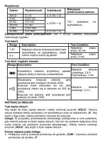
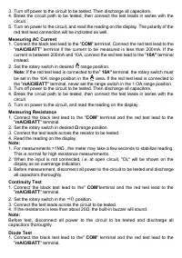
Measuring AC Current
1.
Connect the black test lead to the
"
COM
"
terminal.
Connect the red test lead to the
"
mA/Ω/BATT
"
terminal if the current to be measured is less than 200mA. If the
current is
between 200mA and 10A, connect the red test lead to the
"
10A"
terminal
instead.
2.
Set the rotary switch in desired
range position.
Note:
If the red test lead is connected to the"
10
A"
terminal, the rotary switch must
be set in the 10A range position in the
area.
If the red test lead is connected to
the "
mA/Ω/BATT
"
terminal, never set the range switch in the 1 OA range position.
3.
Turn off power to the circuit to be tested. Then discharge all capacitors.
4.
Break the circuit path to be tested, then connect the test leads in series with the
circuit.
5.
Turn on power to the circuit, and read the reading on the display.
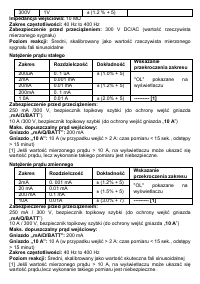
Measuring Resistance
1.
Connect the black test lead to the
"
COM
" terminal and the red test lead to the
"
mA/Ω/BATT
"
terminal.
2.
Set the rotary switch in desired
Ω
range position.
3.
Connect the test leads across the resistor to be tested.
4.
Read the reading on the display.
Note:
1.
For measurements
>1MΩ , the meter may take a few seconds to stabilize reading.
This is normal for high resistance measurements.
2.
When the input is not connected, i.e. at open circuit, "OL"
will be shown on the
display as an overrange indication.
3.
Before measurement, disconnect all power to the circuit to be tested and discharge
all capacitors thoroughly.
Continuity Test
1.
Connect the black test lead to the"
COM
"terminal and the red test lead to the
"
mA/Ω/BATT
"
terminal.
2.
Set the rotary switch in the
position.
3.
Connect the test leads across the circuit to be tested.
4.
If the resistance is less than about 20Ω, the built
-
in buzzer will sound.
Note:
Before test, disconnect all power to the circuit to be tested and discharge all
capacitors thoroughly.
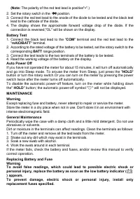
Diode Test
1.
Connect the black test lead to the"
COM
" terminal and the red test lead to the
"
mA/Ω/BATT
"
terminal.


