Материнские платы GIGABYTE GA P55 USB3 rev 2 0 - инструкция пользователя по применению, эксплуатации и установке на русском языке. Мы надеемся, она поможет вам решить возникшие у вас вопросы при эксплуатации техники.
Если остались вопросы, задайте их в комментариях после инструкции.
"Загружаем инструкцию", означает, что нужно подождать пока файл загрузится и можно будет его читать онлайн. Некоторые инструкции очень большие и время их появления зависит от вашей скорости интернета.


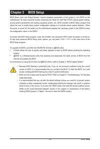


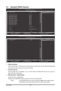

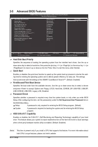


BIOS Setup
- 52 -
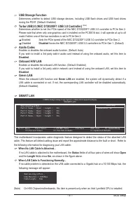
Link Detected Displays transmission speed.
Cable Length Displays the approximate length of the attached LAN cable.
Note: The Gigabit hub will only operate at a speed of 10/100 Mbps in MS-DOS mode; it will operate at a
normal speed of 10/100/1000 Mbps in Windows mode or when the LAN Boot ROM is activated.
When a Cable Problem Occurs...
If a cable problem occurs on a specified pair of wires, the
Status
field will show
Short
and then length
shown will be the approximate distance to the fault or short.
Example:
Part1-2 Status = Short / Length = 2m
Explanation: A fault or short might occur at about 2m on Part 1-2.
Note: Part 4-5 and Part 7-8 are not used in a 10/100 Mbps environment, so their
Status
fields will show
Open
, and the length shown is the approximate length of the attached LAN cable.
Onboard LAN Boot ROM
Allows you to decide whether to activate the boot ROM integrated with the onboard LAN chip.
(Default: Disabled)
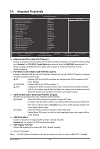
Onboard USB 3.0 Controller (NEC D720200F1 USB Controller)
Enables or disables the NEC D720200F1 USB controller. (Default: Enabled)
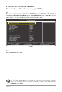
Onboard SATA/IDE Ctrl Mode (GIGABYTE SATA2, IDE and GSATA2_6/7 Connectors)
Enables or disables RAID for the SATA controller integrated in the GIGABYTE SATA2 chip or configures
the SATA controller to AHCI mode.
IDE
Disables RAID for the SATA controller and configures the SATA controller to IDE
mode. (Default)
AHCI
Configures the SATA controller to AHCI mode. Advanced Host Controller Interface
(AHCI) is an interface specification that allows the storage driver to enable advanced
Serial ATA features such as Native Command Queuing and hot plug.
RAID/IDE
Enables RAID for the SATA controller; the IDE controller still operates in IDE mode.
Onboard SATA/IDE Device (GIGABYTE SATA2, IDE and GSATA2_6/7 Connectors)
Enables or disables the IDE and SATA controllers integrated in the GIGABYTE SATA2 chip.
(Default: Enabled)
Onboard Serial Port 1
Enables or disables the first serial port and specifies its base I/O address and corresponding interrupt.
Options are: Auto, 3F8/IRQ4 (default), 2F8/IRQ3, 3E8/IRQ4, 2E8/IRQ3, Disabled.
Onboard Parallel Port
Enables or disables the onboard parallel port (LPT) and specifies its base I/O address and correspond
-
ing interrupt. Options are: 378/IRQ7 (default), 278/IRQ5, 3BC/IRQ7, Disabled.
Parallel Port Mode
Selects an operating mode for the onboard parallel (LPT) port. Options are: SPP (Standard Parallel Port)
(default), EPP (Enhanced Parallel Port), ECP (Extended Capabilities Port), ECP+EPP.


