Измерительные приборы Condtrol Xliner Duo 360 - инструкция пользователя по применению, эксплуатации и установке на русском языке. Мы надеемся, она поможет вам решить возникшие у вас вопросы при эксплуатации техники.
Если остались вопросы, задайте их в комментариях после инструкции.
"Загружаем инструкцию", означает, что нужно подождать пока файл загрузится и можно будет его читать онлайн. Некоторые инструкции очень большие и время их появления зависит от вашей скорости интернета.

10
11
user manual
C R O S S
L I N E L A S E R
EN
user manual
C R O S S
L I N E L A S E R
EN
XLiner Duo/Combo 360
XLiner Duo/Combo 360
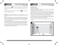
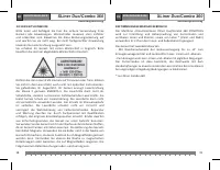
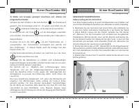
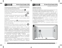
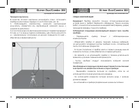
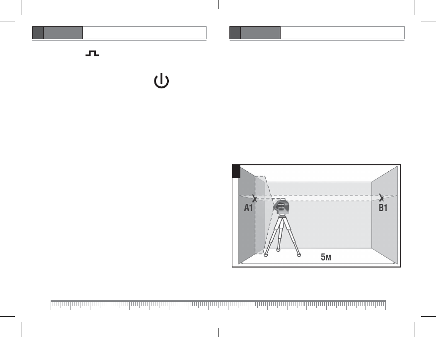
ACCURACY CHECK
Check of horizontal line
Check of horizontal line is carried out by using 2 walls A and B located
opposite each other at 5m distance.
1. Install the laser level as close as possible to wall A (see Fig.A). Unlock
compensator and switch on vertical and horizontal lines. Expand the
device emitters in the direction of wall A so that the crossing of the
laser lines on the wall is located in front of the laser level. Mark the
crossing point of laser lines as A1. Mark point B on the wall B.
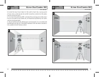
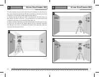
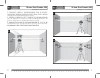
2. Turn the instrument by 90°. Check misalignment of horizontal line
and point B1 (see Fig. B). If deviation between the laser line and the B1
mark exceeds 1 mm, please contact service center.
3. Repeat step 2 for 2 more times, turning the laser level in one
direction.
A
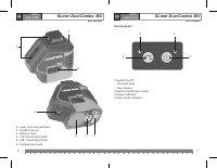
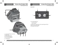
Shor t press button to switch on/of f pulse mode that allows
working with laser receiver. In this mode pulse mode indicator will
turn red.
To switch the laser level of f shor t press button several times
until all laser planes are of f.
Attention!
To increase operating time and avoid the risk of
unintentional blindness switch the laser on only when you are ready
to work.
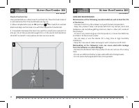
If operated near objects or air streams with the temperature dif ferent
from the environment the laser line may tremble due to heterogeneity
of the atmosphere. The longer the distance, the more trembling of the
laser line can be obser ved.
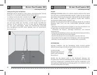
The width of the laser line increases as soon as operating distance
increases as well. The layout should be made along the axis of the laser
line. For maximum accuracy, use the middle por tion of the laser line.
It should be noted that the shape of the laser line on the object ’s
surface (e.g., walls, ceilings, etc.) depends on the cur vature and tilt of
the surface relative to the laser plane.
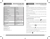
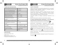
Характеристики

Остались вопросы?Не нашли свой ответ в руководстве или возникли другие проблемы? Задайте свой вопрос в форме ниже с подробным описанием вашей ситуации, чтобы другие люди и специалисты смогли дать на него ответ. Если вы знаете как решить проблему другого человека, пожалуйста, подскажите ему :)


