Измерительные приборы Condtrol XLiner Combo - инструкция пользователя по применению, эксплуатации и установке на русском языке. Мы надеемся, она поможет вам решить возникшие у вас вопросы при эксплуатации техники.
Если остались вопросы, задайте их в комментариях после инструкции.
"Загружаем инструкцию", означает, что нужно подождать пока файл загрузится и можно будет его читать онлайн. Некоторые инструкции очень большие и время их появления зависит от вашей скорости интернета.

XLiner / XLiner Combo CONDTROL
XLiner / XLiner Combo CONDTROL
36
37
user manual
user manual
EN
EN
The dif ference L between both marked points I and III on the wall A indicates
the actual height deviation of the instrument.
The maximum permitted deviation L is calculated as follows:
L = double distance between the walls x 0.2 mm/m
Example: With a 5 meter distance between the walls the maximum deviation is
L = 2 x 5m x 0.2 mm/m = 2 mm,
thus, the marks must not be more than 2 mm apart.
When the maximum deviation exceeds 2 mm, you should contact CONDTROL
ser vice centre.
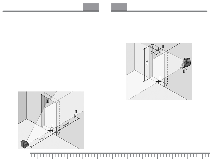
Checking of the vertical line
For this check, a door opening is required with at least 2.5 meters of space
(on a firm sur face) to each side of the door.
Position the instrument at a distance of 2.5 meters away from the door
opening on a firm sur face (not on a tripod). Allow the instrument to level
in while in cross-line operation and direct the laser beam against the door
opening.
Mark the centre of the vertical laser line at the floor of the door opening (point I),
at a distance of 5 meters beyond the other side of the door opening (point II) and
at the upper edge of the door opening (point III).
Position the instrument on the other side of the door opening directly behind
point II. Allow the instrument to level in and align the ver tical laser line in
such a manner that its centre runs exactly through points I and II.
The dif ference L between point III and the centre of the laser line at the upper
edge of the door opening results in the actual deviation of the instrument
from the ver tical plane.
Measure the height of the door opening.
The maximum permitted deviation L is calculated as follows:
L = double height of the door opening x 0.2 mm/m
Example: With a door opening height of 2 meters, the maximum permit ted
deviation is
L = 2 x 2 m x 0.2 mm/m = 0.8 mm,
thus, the marks must not be more than 0.8 mm apar t.
Содержание
- 5 УКАЗАНИЯ ПО БЕЗОПАСНОСТИ
- 6 Расширенный комплек т поставки; G Крышка батарейного отсека
- 7 Установка/смена батареи
- 8 Выключайте; Не направляйте
- 9 Д ля работы без автоматического компенсирования т умблер; Проверка точности; Влияние на точность
- 10 Контроль вертикальной линии
- 11 Разница L меж ду точкой III и серединой лазерной линии на верхнем
- 12 ИСПОЛЬЗОВАНИЕ ПРИБОРА С ДОПОЛНИТЕЛЬНЫМИ АКСЕССУАРАМИ*
- 13 работы с автоматическим компенсированием.; ТЕХОБСЛУЖИВАНИЕ И РЕМОНТ; Оставляем за собой право на изменения.


