Измерительные приборы Condtrol Neo G 220 set - инструкция пользователя по применению, эксплуатации и установке на русском языке. Мы надеемся, она поможет вам решить возникшие у вас вопросы при эксплуатации техники.
Если остались вопросы, задайте их в комментариях после инструкции.
"Загружаем инструкцию", означает, что нужно подождать пока файл загрузится и можно будет его читать онлайн. Некоторые инструкции очень большие и время их появления зависит от вашей скорости интернета.

10
11
user manual
C R O S S
L I N E L A S E R
EN
user manual
C R O S S
L I N E L A S E R
EN
CONDTROL NEO G220 Set
CONDTROL NEO G220 Set
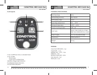
OPERATION
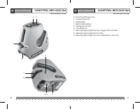
Before star t operation remove the batter y cover, inser t the batteries,
obser ving correct polarity. Put batter y cover back.
Use alkaline A A batteries only, all batteries should be of the same type
and brand with the same charge level. Replace batteries if batter y
charge level indicator turns red while operation.
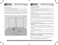
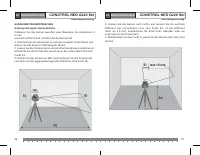
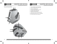
Place an instrument on a firm and stable surface or a tripod.
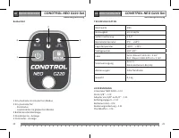
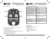
Move the switch bar to choose necessar y operating mode:
1) Automatic levelling, to build horizontal and vertical planes and
lines:
Move the switch bar to unlocked position . Compensator is
unlocked. If the product is out of the range of automatic compensation
it will emit sound signal.
Shor t press button to turn on necessar y laser planes.
Shor t press button to turn on/of f pulse mode that allows
working with laser receiver. In this mode pulse mode indicator will
turn green.
To switch of f the product move the switch bar to locked position .
1) Locked compensator, to build inclined planes and lines:
Move the switch bar to locked position . Compensator is locked.
Shor t press button to turn on the product. Horizontal plane
will switch on. Locked pendulum indicator turns red.
Shor t press button to turn on necessar y laser planes.
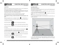
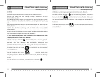
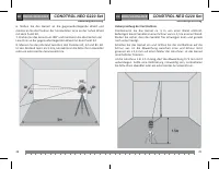
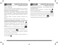
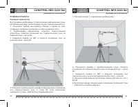
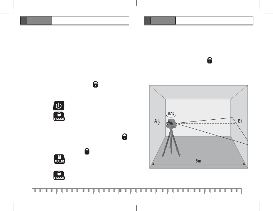
ACCURACY CHECK
Check of horizontal line
Check of horizontal line is carried out by using 2 walls located opposite
each other at a distance of 5m.
1. Put the instrument as close as possible to the wall so that laser
emitters are located opposite the wall.
2. Move lever lock to unlocked position and switch on horizontal
plane.
Mark location of horizontal line on the wall as A1.
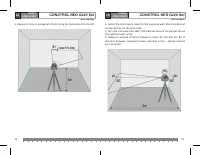
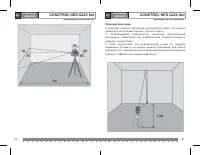
3. Turn the instument by 180° and mark location of horizontal line on
another wall as B1.
4. Turn the instrument to the right. Measure ver tical deviation of
horizontal line from point B1. If deviation exceeds 1,5 mm – please
contact ser vice center.
Характеристики

Остались вопросы?Не нашли свой ответ в руководстве или возникли другие проблемы? Задайте свой вопрос в форме ниже с подробным описанием вашей ситуации, чтобы другие люди и специалисты смогли дать на него ответ. Если вы знаете как решить проблему другого человека, пожалуйста, подскажите ему :)


