
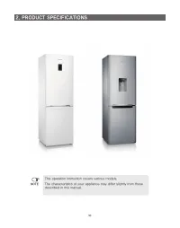
Холодильник Samsung RB37A5290SA - инструкция пользователя по применению, эксплуатации и установке на русском языке. Мы надеемся, она поможет вам решить возникшие у вас вопросы при эксплуатации техники.
Если остались вопросы, задайте их в комментариях после инструкции.
"Загружаем инструкцию", означает, что нужно подождать пока файл загрузится и можно будет его читать онлайн. Некоторые инструкции очень большие и время их появления зависит от вашей скорости интернета.


60
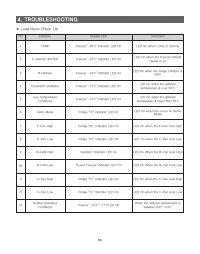
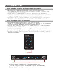
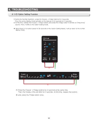
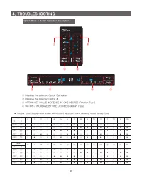
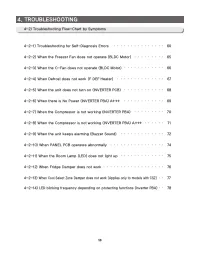
4. TROUBLESHOOTING
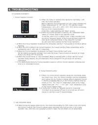
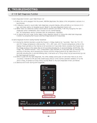
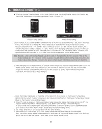
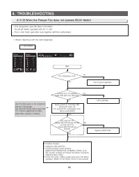
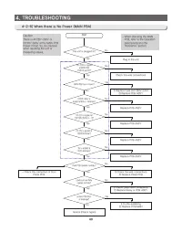
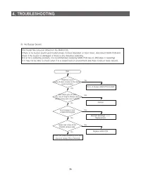
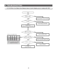
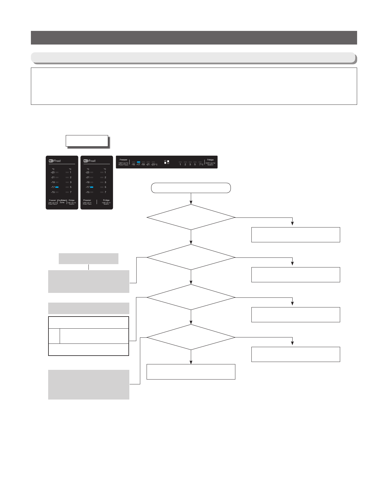
4-2-1) When Self-Diagnosis Error occurs
- The Display Panel shows the Sensor Error and, when the unit is plugged in and there are sensor errors, the unit does not
operate and LED related to the defective sensors keep blinking.
- When sensor defects occur during the operation, the unit keeps working. But, it shifts to the Emergency Operation and it
may not work properly. So, please check the unit according to the Self Diagnosis function.
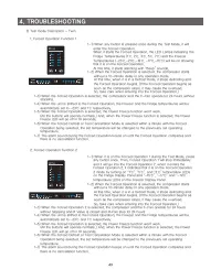
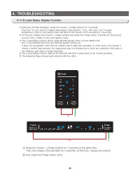
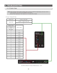
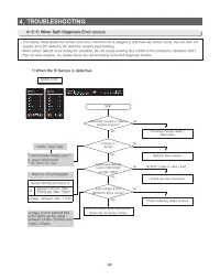
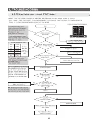
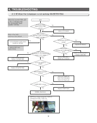
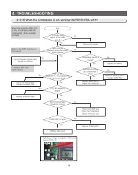
1) When the R-Sensor is defective
ERROR CODE
MAIN PCB Connector CN30 is
inserted properly?
R Sensor is
normal?
Voltage between MAIN PCB
Connector CN30-"5"(ORG)
and CN30-"7"(GRY)?
Input Voltage at IC10
MICOM Pin #23 is normal?
Start
PCB and Temp Sensor are normal.
Check the connector contact.
Connector contact defect /
Reconnect
Replace Temp Sensor
Check the wire connection
Check Soldering Defect & Short
No
No
No
NO (0.6V > Value or Value > 4.6V)
No
Yes
Yes
Yes
Yes
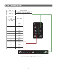
Sensor MICOM/Connector #
R
Between Connector CN30-
"5"(ORG) and CN30-"7"(GRY)
Voltage : Between 4.6V ~ 0.6V
** Sensor Resistance Reading Location **
R : Between CN30 #5 and #7
** 0Ω : Short / ∞Ω : Open
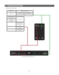
Voltage at IC10 MICOM #23
is the same as the value
between CN30-"5"(ORG) and
CN30-"7"(GRY)
Refer to Circuit Diagram
DATA1. Temp Table
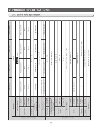
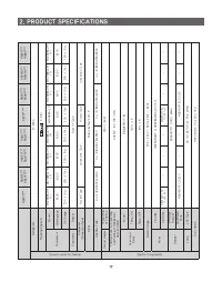
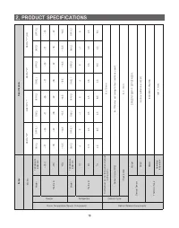
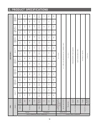
Характеристики

Остались вопросы?Не нашли свой ответ в руководстве или возникли другие проблемы? Задайте свой вопрос в форме ниже с подробным описанием вашей ситуации, чтобы другие люди и специалисты смогли дать на него ответ. Если вы знаете как решить проблему другого человека, пожалуйста, подскажите ему :)


