
Холодильник Liebherr IKS 2254 Comfort - инструкция пользователя по применению, эксплуатации и установке на русском языке. Мы надеемся, она поможет вам решить возникшие у вас вопросы при эксплуатации техники.
Если остались вопросы, задайте их в комментариях после инструкции.
"Загружаем инструкцию", означает, что нужно подождать пока файл загрузится и можно будет его читать онлайн. Некоторые инструкции очень большие и время их появления зависит от вашей скорости интернета.

6
IK/IKP/IKB/IG
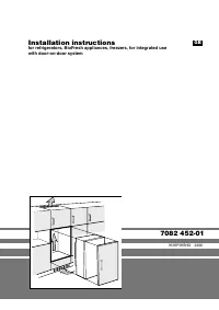
Installation instructions
W
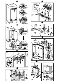
Fig.
J
: Suspend the unit door on the door of the appliance/
adjusting pins do. Screw the counternuts
dn
loosely onto
the adjusting pins. Close the door.
W
Fig.
J1
: Check the gap between the door and the surround-
ing unit doors.
- Fig.
J2
: Align the unit door flush with the surrounding unit
fronts: align laterally (
X
) by sliding in the corresponding
direction, adjust height (
Y
) and lateral tilt with the adjusting
pins
do
using a screwdriver.
- Tighten counternuts
dn
.
W
Fig.
K
:
Secure the mounting bracket
cr
to the pre-drilled
holes in the appliance door using the hexagonal screw
cs
.
W
Screw the appliance door onto the unit door with the at-
tachment brackets
cr
:
- Ensure that both metal edges are flush (symbol
//
). Drill at-
tachment holes (making a hole with a bradawl) and screw
tight.
W
Adjust the depth of the unit door (
Z
):
- Fig.
J2
: top: loosen screws
dp
,
- Fig.
K
: bottom: loosen the hexagonal screws
cs
with the
ring spanner
co
provided and adjust the door.
- Fig.
J1
: Allow an air gap of approx. 2 mm between the unit
door and the body of the unit. Do not allow knobs and seal-
ing lips to make contact with the appliance as this can have
a detrimental effect on its function.
W
Fig.
L
: If the unit door is large or divided into separate parts,
attach another pair of attachment brackets
cr
(accessories
bag, fig.
C3
).Use the pre-drilled holes in the handle area of
the appliance door.
W
Check that the door is properly positioned, and readjust if
necessary. Tighten all screws.
- Fig.
L1
: Tighten the counternuts
dn
with the ring span-
ner
co
provided, holding the adjusting pins
do
in position
with a screwdriver.
W
Fig.
L2
: If necessary, align the equaliser trim
bm
parallel
with the floor of the unit. It must not project.
W
Fig.
L3
: Fix the appliance in the round hole at the bottom
with the second screw
bu
through the plastic bracket.
W
Fig.
M
: Fit all the covers:
-
Place the top cover
cl
in position and click into place.
- Place lateral cover
cm
in position, slide it to the limit, then
press on the cover until it audibly engages.
- Slide on cover
ct
laterally, draw the cover forwards using a
screwdriver according to fig.
M
so that it engages well into
place.
W
Fig.
N
: The opening resilience of the door can now be
adjusted. Adjust using the no. 5 Allen key provided.
- Turn clockwise for stronger resilience.
- Turn anticlockwise for = weaker resilience (factory setting).
_______________________________________________
The manufacturer works constantly on the further develop-
ment of all the types and models. Therefore please under-
stand that we have to reserve the right to make design, equip-
ment and technical modifications.
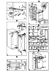
Installation and fitting
Figs.
C1-3
:All installation components are supplied.
W
Fig.
D
: Fit equaliser trim
bm
centered on the appliance:
slide into the channel and engage in the key holes.
W
Route the mains cable with the aid of string
1
in such a way
that the appliance can be easily connected after installation.
W
Slide the appliance three-quarters of the way into the
recess.
W
Note the thickness of the unit walls:
For 16 mm unit wall
(568 mm recess):
- Fig.
D
: Stick sealing strip
bp
onto the side of the appliance
on the handle side flush with the front: remove the protec-
tive film and stick on; shorten to recess height if necessary.
- Clip spacers
bo
and
bq
onto the hinges.
- Fig.
E
: Slide appliance into the recess until the spacers
make contact with the side of the units, Fig.
E1
.
For 19 mm unit wall
= 562 mm recess:
- Fig.
E2
: Slide the appliance into the recess until the fronts
of the hinges are flush with the sides of the unit walls; note
the additional space needed for units with door furniture
(knobs, sealing lips, etc.). Allow the hinges to protrude by
the additional distance required. Press the appliance on
the hinge side against the wall of the unit.
W
Fig.
E3
: Level the appliance by adjusting the adjustable
feet with the spanner provided
cn
. Align the body of the
appliance parallel to the front edges of the side walls of the
unit.
W
Screw plastic bracket
br
onto the handle side of the appli-
ance with M5 screws
bs
.
- Make sure the front of the plastic bracket
br
is flush with
the front edge of the floor of the unit.
Do not forget the additional space required if the unit has
door furniture (knobs, sealing lips, etc.) and align parallel to
the front edge of the hinge.
W
Fig.
F
: Screw the appliance into the recess.
- Figs.
F1/2
: Screw in with long wood board screws
bu
through the hinge plates at the top and bottom.
- Fig.
F3
: Screw in temporarily with a long screw
bu
through
the middle of the long slot on the plastic bracket
br
. Fold
up the cover on the plastic bracket and close the appliance
door.
Fitting the unit door
W
Fig.
G1
: Check the 8 mm default setting (distance between
appliance door and bottom edge of attachment strut).
W
Fig.
G
: Slide the fitting aids
dl
up level with the unit door,
underside of stop edge
▲
of fitting aid =
upper edge of unit
door
W
Fit the attachment strut
dm
on the unit door:
- For this purpose, unscrew the strut by way of the counter-
nuts
dn
fig.G
- Fig.
H
: Suspend the strut with the fitting aids
dl
on the
inside of the unit door and align centrally (draw a short line
in the middle of the unit door, align the arrow on the strut
with it keeping the same distance to outer edges on left
and right).
W
Fasten the attachment strut
dm
in the centre:
- Fig.
H
: with at least 6 screws if the doors are made
of wood board,
- with 4 screws round the edge in the case of panel doors.
- Lift the fitting aids
dl
out to the top, turn round and insert
into the adjacent openings.
Характеристики

Остались вопросы?Не нашли свой ответ в руководстве или возникли другие проблемы? Задайте свой вопрос в форме ниже с подробным описанием вашей ситуации, чтобы другие люди и специалисты смогли дать на него ответ. Если вы знаете как решить проблему другого человека, пожалуйста, подскажите ему :)


