
Холодильник Liebherr IKS 2254 Comfort - инструкция пользователя по применению, эксплуатации и установке на русском языке. Мы надеемся, она поможет вам решить возникшие у вас вопросы при эксплуатации техники.
Если остались вопросы, задайте их в комментариях после инструкции.
"Загружаем инструкцию", означает, что нужно подождать пока файл загрузится и можно будет его читать онлайн. Некоторые инструкции очень большие и время их появления зависит от вашей скорости интернета.
5
IK/IKP/IKB/IG
Installation instructions
Keep the installation instructions in a safe place and pass
them on to the next owner of your appliance where applica-
ble.
The operating instructions apply to several
models. Differences may therefore occur.
Before reading, please fold out and refer
to the illustrated front page.
You additionally require the following tool for installation:
Cordless screwdriver Torx
®
15, 20, 25, spanner 13.
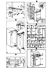
Changing over door hinges
Fig.
A1
The door hinges can be changed from one side to
the other if need be. Otherwise continue from "Installation
information", fig.
B
.
W
To simplify installation, slide the appliance three-quarters
of the way into the recess. Open the door.
For models with soft stop
3
* proceed according to fig.
A
(otherwise continue according to fig.
A1
).
For appliances 870 mm high: remove the lower storage rack
for easier installation.
W
Fig.
A
: Detach the soft stop mechanism:
Please note
the soft stop mechanism contracts
in the detached state!
W
Take hold of cover
1
at the back for removal,
bend it downwards a little and push it away to the side.
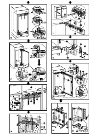
W
Undo screw
2
, while pressing the fork of the soft stop
mechanism downwards so that it cannot suddenly disen-
gage.
W
Carefully disengage the fork of the soft stop mechanism
from the hinge - the mechanism contracts!
W
Unscrew the ball stud
4
together with the soft stop
mechanism from the door and set it aside.
W
Fig.
A1,
lift off cover parts
5
,
6
and
7
in a forward
direction using a flat-blade screwdriver.
W
Detail fig.
A1.1
: Loosen t
h
e attachment screws
8
on the
top and bottom of the body of the appliance.
- Pull the door outwards and remove.
W
Transfer the attachment screws
8
to the other side and
screw in a little way.
W
Fig.
A1
:
Unscrew the door attachment screws
9
and
replace the hinges in the diagonally opposite corner.
NB:
Do not fold the hinges together - danger of injury!
- Use a cordless screwdriver to screw down the hinges
- the screws
9
are self-tapping.
W
Close the holes on the other side with the plugs
bl
.
W
Suspend the appliance door in the ready inserted
screws
8
and tighten screws.
W
Fig.
A
: Fit the soft stop mechanism
3
* back in place:
Screw ball stud
4
together with soft stop mechanism into
the new fastening hole.
W
Draw the fork out of the soft stop mechanism, put it over
the hinge and attach with the stud.
W
Re-fasten with screw
3
, while pressing the fork onto the
hinge so that it does not disengage.
W
Fit all the cover parts back in place.
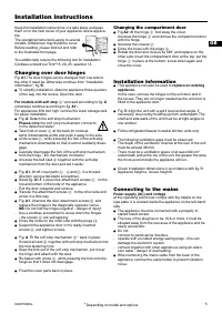
Changing the compartment door
W
Fig.
A2
: At the hinge
1
fold away the cover.
Unscrew the hinge
1
and remove the compartment door
with the hinge.
W
Unscrew the closure
2
.
W
Close the holes with the plugs
3
.
W
Rotate the door and closure by 180° and replace on the
other side: Insert the compartment door at the top, put the
hinge
1
in place at the bottom, screw down again and
close the cover.
Installation information
W
This appliance can also be used to
replace an existing
appliance
.
In this case, remove the hinges on the unit door and in
the recess. They are no longer needed as the unit door is
fitted to the appliance door.
W
Fig. B: Align the unit with a spirit level and an angle. If
necessary, level out by building up from underneath. The
shelf and side walls of the unit must be at right-angles to
one another.
W
Fit the refrigerator/freezer in stable kitchen units only.
W
The following ventilation gaps must be observed:
- The depth of the ventilation channel at the rear of the unit
must be at least 38 mm.
- There must be a ventilation space of at least 200 cm
2
underneath and at the top of the unit. the greater the area
the more economically the appliance will run.
W
Check installation dimensions in accordance with fig. B:
Appliance height a, recess height b
Connecting to the mains
Power supply (AC) and voltage
at the operating point must comply with the details on the
type plate. It is located inside the appliance on the left-hand
side.
W
The appliance must be connected with a properly in-
stalled fused socket.
W
The fuse of the plug has to be 10 A or more, it must be
situated away from the rear area of the appliance and be
easily accessible.
W
Do not
- connect to stand-alone inverters,
- operate with so-called energy-saving plugs - this can
damage the electronic system.
- connect together with other appliances using an exten-
sion cable - danger of overheating.
W
When removing the mains cable from the back of the
appliance, remove the cable holder to prevent vibration
noise.
*
Depending on model and options
GB
Характеристики

Остались вопросы?Не нашли свой ответ в руководстве или возникли другие проблемы? Задайте свой вопрос в форме ниже с подробным описанием вашей ситуации, чтобы другие люди и специалисты смогли дать на него ответ. Если вы знаете как решить проблему другого человека, пожалуйста, подскажите ему :)


