
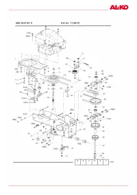
Газонокосилки Al-ko BM 875 III 112872 - инструкция пользователя по применению, эксплуатации и установке на русском языке. Мы надеемся, она поможет вам решить возникшие у вас вопросы при эксплуатации техники.
Если остались вопросы, задайте их в комментариях после инструкции.
"Загружаем инструкцию", означает, что нужно подождать пока файл загрузится и можно будет его читать онлайн. Некоторые инструкции очень большие и время их появления зависит от вашей скорости интернета.


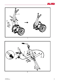


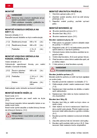


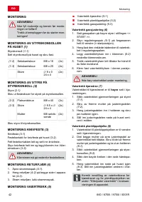


Assembly of the runners on the scythe attachment
474834_a
13
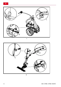
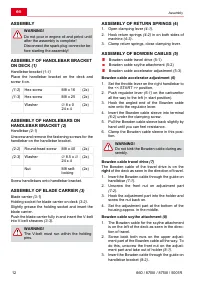
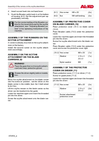
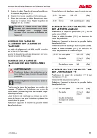
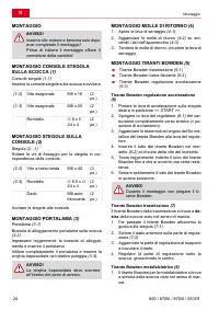
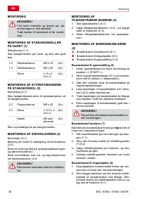
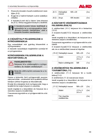
4. Insert curved hook into red hand lever.
5. Hook the Bowden cable back in at the bottom
of housing
(8-3)
. Set the adjustment part ap-
proximately centrally.
ADVICE
For the correct setting of the Bowden ca-
bles for the travel drive and for the scythe
attachment, see: "Adjusting Bowden ca-
bles" in the operating instructions of the
machine.
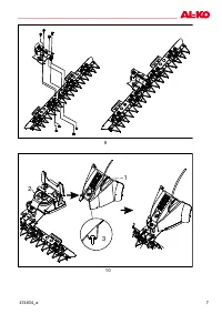
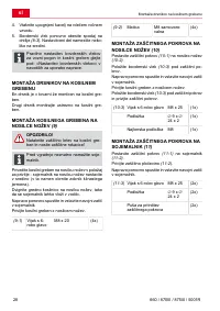
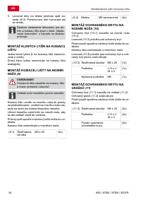
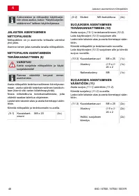
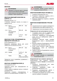
ASSEMBLY OF THE RUNNERS ON THE
SCYTHE ATTACHMENT
A runner is already mounted on the scythe attach-
ment at the factory.
Install the second runner on the scythe attach-
ment accordingly.
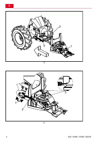
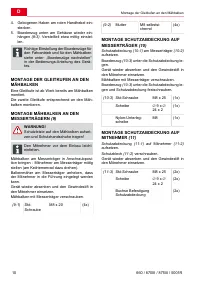
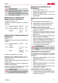
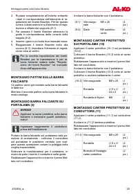
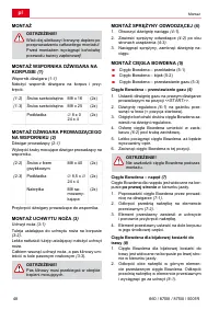
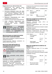
ASSEMBLY ON THE SCYTHE
ATTACHMENT ON THE BLADE
CARRIERS
(9)
WARNING!
Place the guard bar on the scythe attach-
ment and wear protective gloves!
ADVICE
Grease the driver slightly before installa-
tion.
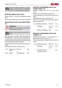
Move the scythe attachment on the blade carrier
into the screw-on position - set the driver on the
blade carrier in the middle (turn the V-belt wheel
to do this).
Lift the scythe mower on the blade carrier so the
driver can be inserted into the guide.
Lower the machine again and insert the threaded
pin into the driver.
Screw the scythe attachment onto the blade car-
rier.
(9-1)
Hex screw
M8 x 20
(4x)
(9-2)
Nut
M8 self-locking
(4x)
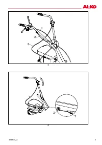
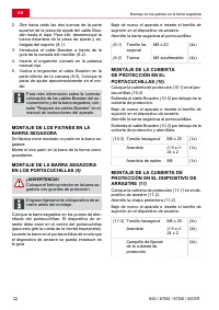
ASSEMBLY OF PROTECTIVE COVER
ON BLADE CARRIER
(10)
Place protective cover
(10-1)
on blade carrier
(10-2)
.
Place Bowden cable
(10-3)
under the protective
cover.
Lower the machine again and insert the threaded
pin into the driver.
Screw the scythe attachment onto the blade car-
rier.
Place Bowden cable
(10-3)
under the protective
cover and screw the protective cover tight.
(10-3)
Hex screw
M8 x 25
(1x)
Washer
∅
9 x
∅
24 x 2
(1x)
Nylon washer
M8
(1x)
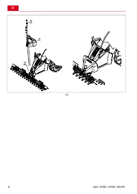
ASSEMBLY OF THE PROTECTIVE
COVER ON DRIVER
(11)
Place protective cover
(11-1)
on driver
(11-2)
.
Screw on guard plate
(11-2)
.
Lower the machine again and insert the threaded
pin into the driver.
(11-3)
Hex screw
M8 x 25
(2x)
Washer
∅
9 x
∅
24 x 2
(2x)
Socket attachment
protective cover
(2x)


