
Фрезеры Makita RT0700CX2 - инструкция пользователя по применению, эксплуатации и установке на русском языке. Мы надеемся, она поможет вам решить возникшие у вас вопросы при эксплуатации техники.
Если остались вопросы, задайте их в комментариях после инструкции.
"Загружаем инструкцию", означает, что нужно подождать пока файл загрузится и можно будет его читать онлайн. Некоторые инструкции очень большие и время их появления зависит от вашей скорости интернета.


11
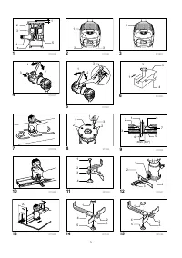
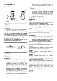
Fig.8
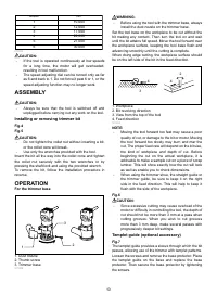
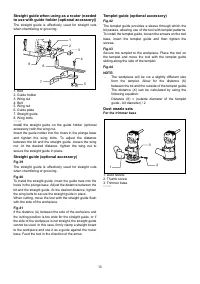
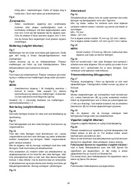
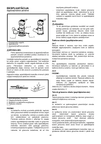
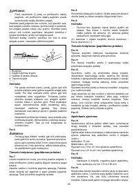
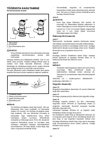
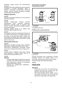
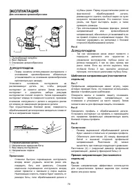
Secure the templet to the workpiece. Place the tool on
the templet and move the tool with the templet guide
sliding along the side of the templet.
Fig.9
NOTE:
•
The workpiece will be cut a slightly different size
from the templet. Allow for the distance (X)
between the router bit and the outside of the
templet guide. The distance (X) can be calculated
by using the following equation:
Distance (X) = (outside diameter of the templet guide -
router bit diameter) / 2
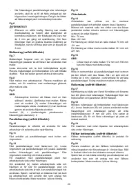
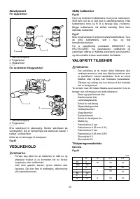
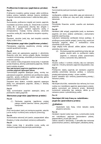
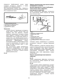
Straight guide (optional accessory)
Fig.10
The straight guide is effectively used for straight cuts
when chamfering or grooving.
Fig.11
Attach the guide plate to the straight guide with the bolt
and the wing nut.
Fig.12
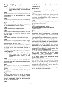
Attach the straight guide with the clamp screw (A).
Loosen the wing nut on the straight guide and adjust the
distance between the bit and the straight guide. At the
desired distance, tighten the wing nut securely.
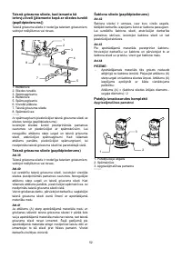
When cutting, move the tool with the straight guide flush
with the side of the workpiece.
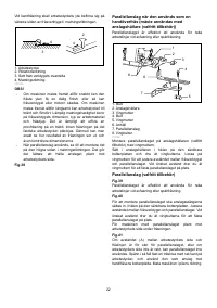
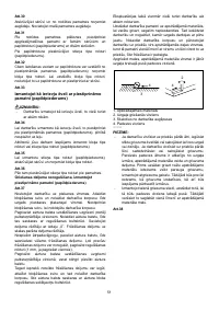
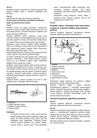
If the distance (A) between the side of the workpiece and
the cutting position is too wide for the straight guide, or if
the side of the workpiece is not straight, the straight guide
cannot be used. In this case, firmly clamp a straight board
to the workpiece and use it as a guide against the trimmer
base. Feed the tool in the direction of the arrow.
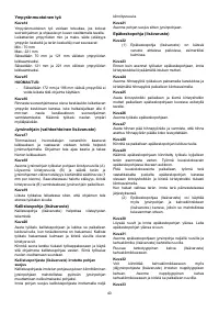
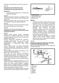
Fig.13
Circular work
Fig.14
Circular work may be accomplished if you assemble the
straight guide and guide plate as shown in the figures.
Min. and max. radius of circles to be cut (distance
between the center of circle and the center of bit) are as
follows:
Min.: 70 mm
Max.: 221 mm
For cutting circles between 70 mm and 121 mm in radius.
For cutting circles between 121 mm and 221 mm in
radius.
Fig.15
NOTE:
•
Circles between 172 mm and 186 mm in radius
cannot be cut using this guide.
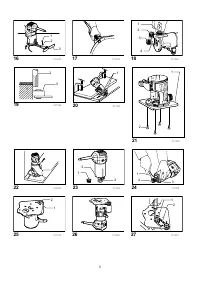
Fig.16
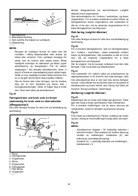
Align the center hole in the straight guide with the center
of the circle to be cut. Drive a nail less than 6 mm in
diameter into the center hole to secure the straight guide.
Pivot the tool around the nail in clockwise direction.
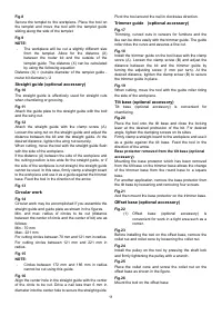
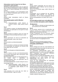
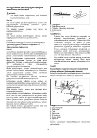
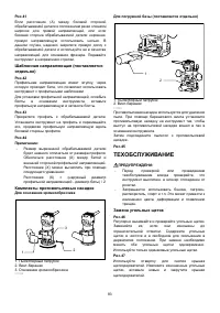
Trimmer guide (optional accessory)
Fig.17
Trimming, curved cuts in veneers for furniture and the
like can be done easily with the trimmer guide. The guide
roller rides the curve and assures a fine cut.
Fig.18
Install the trimmer guide on the tool base with the clamp
screw (A). Loosen the clamp screw (B) and adjust the
distance between the bit and the trimmer guide by
turning the adjusting screw (1 mm per turn). At the
desired distance, tighten the clamp screw (B) to secure
the trimmer guide in place.
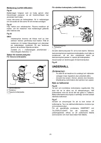
Fig.19
When cutting, move the tool with the guide roller riding
the side of the workpiece.
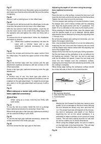
Tilt base (optional accessory)
Tilt base (optional accessory) is convenient for
chamfering.
Fig.20
Place the tool onto the tilt base and close the locking
lever at the desired protrusion of the bit. For desired
angle, tighten the clamping screws on its sides.
Firmly clamp a straight board to the workpiece and use it
as a guide against the tilt base. Feed the tool in the
direction of the arrow.
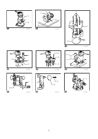
Base protector removed from the tilt base (optional
accessory)
Mounting the base protector which has been removed
from the tilt base on the trimmer base allows the change
of the trimmer base from the round base to a square
base.
For another application, remove the base protector from
the tilt base by loosening and removing four screws.
Fig.21
And then mount the base protector on the trimmer base.
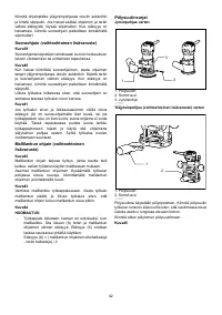
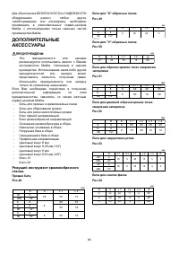
Offset base (optional accessory)
Fig.22
(1) Offset base (optional accessory) is
convenient for work in a tight area such as a
corner.
Fig.23
Before installing the tool on the offset base, remove the
collet nut and collet cone by loosening the collet nut.
Fig.24
Install the pulley on the tool by pressing the shaft lock
and firmly tightening the pulley with a wrench.
Fig.25
Place the collet cone and screw the collet nut on the
offset base as shown in the figure.
Fig.26
Mount the tool on the offset base
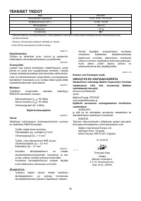
Характеристики

Остались вопросы?Не нашли свой ответ в руководстве или возникли другие проблемы? Задайте свой вопрос в форме ниже с подробным описанием вашей ситуации, чтобы другие люди и специалисты смогли дать на него ответ. Если вы знаете как решить проблему другого человека, пожалуйста, подскажите ему :)


