
Фрезеры Makita RP0900 - инструкция пользователя по применению, эксплуатации и установке на русском языке. Мы надеемся, она поможет вам решить возникшие у вас вопросы при эксплуатации техники.
Если остались вопросы, задайте их в комментариях после инструкции.
"Загружаем инструкцию", означает, что нужно подождать пока файл загрузится и можно будет его читать онлайн. Некоторые инструкции очень большие и время их появления зависит от вашей скорости интернета.


6
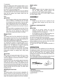
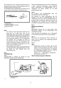
"0" graduation.
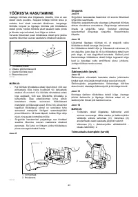
Raise the stopper pole until the desired depth of cut is
obtained. The depth of cut is indicated on the scale (1
mm per graduation) by the depth pointer. Then tighten
the screw to secure the stopper pole.
Now, your predetermined depth of cut can be obtained
by loosening the lock lever and then lowering the tool
body until the stopper pole makes contact with the
adjusting hex bolt.
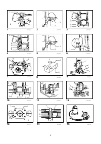
Fig.3
CAUTION:
•
Since excessive cutting may cause overload of the
motor or difficulty in controlling the tool, the depth
of cut should not be more than 15 mm at a pass
when cutting grooves with an 8 mm diameter bit.
•
When cutting grooves with a 20 mm diameter bit,
the depth of cut should not be more than 5 mm at a
pass.
When you wish to cut grooves more than 15 mm
deep with an 8 mm diameter bit or more than 5 mm
deep with a 20 mm diameter bit, make several
passes with progressively deeper bit settings.
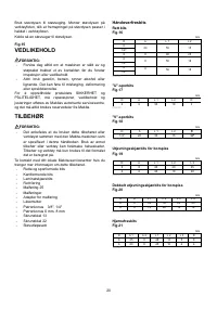
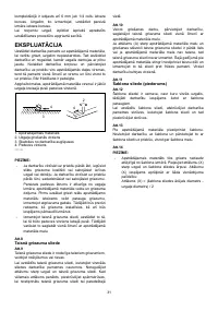
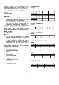
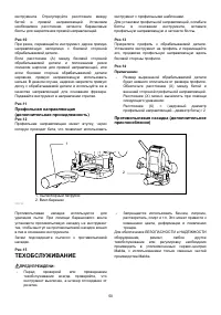
Stopper block
Fig.4
The stopper block has three adjusting hex bolts which
raise or lower 0.8 mm per turn. You can easily obtain
three different depths of cut using these adjusting hex
bolts without readjusting the stopper pole.
Adjust the lowest hex bolt to obtain the deepest depth of
cut, following the method of "Adjusting depth of cut".
Adjust the two remaining hex bolts to obtain shallower
depths of cut. The differences in height of these hex
bolts are equal to the differences in depths of cut.
To adjust the hex bolts, turn the hex bolts. The stopper
block is also convenient for making three passes with
progressively deeper bit settings when cutting deep
grooves.
CAUTION:
When using a bit having total length of 60 mm or more,
or edge length of 35 mm or more, the depth of cut
cannot be adjusted as previously mentioned. To adjust,
proceed as follows:
Loosen the lock lever and carefully adjust bit protrusion
below the tool base to the desired depth of cut by
moving the tool body up or down. Then retighten the lock
lever to lock the tool body at that depth of cut. Keep the
tool body locked at this position during use. Since the bit
always protrudes from the tool base, be careful when
handling the tool.
Adjusting the lock lever
Fig.5
The locked position of the lock lever is adjustable. To
adjust it, remove the screw securing the lock lever. The
lock lever will come off. Set the lock lever at the desired
angle. After adjustment, tighten the lock lever clockwise.
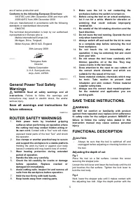
Switch action
Fig.6
CAUTION:
•
Before plugging in the tool, always check to see
that the switch trigger actuates properly and
returns to the "OFF" position when released.
To start the tool, simply pull the switch trigger. Release
the switch trigger to stop.
ASSEMBLY
CAUTION:
•
Always be sure that the tool is switched off and
unplugged before carrying out any work on the
tool.
Installing or removing the bit
Fig.7
CAUTION:
•
Install the bit securely. Always use only the
wrenches provided with the tool. A loose or
overtightened bit can be dangerous.
•
Do not tighten the collet nut without inserting a bit.
It can lead to breakage of the collet cone.
Insert the bit all the way into the collet cone and tighten
the collet nut securely with the two wrenches.
A 6 mm or 1/4" collet cone is also provided as standard
equipment besides the 8 mm or 3/8" collet cone that is
factory installed on the tool. Use the correct size collet
cone for the bit which you intend to use.
To remove the bit, follow the installation procedure in
reverse.
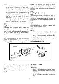
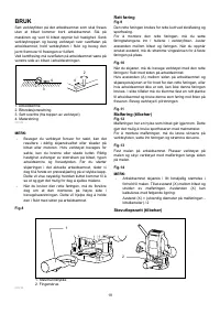
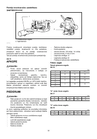
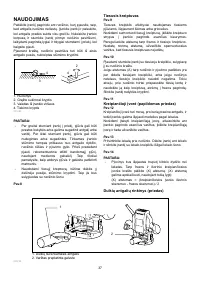
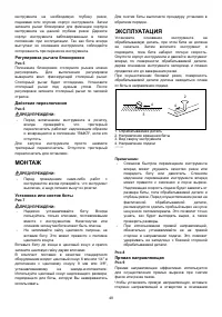
OPERATION
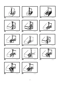
Set the tool base on the workpiece to be cut without the
bit making any contact. Then turn the tool on and wait
until the bit attains full speed. Lower the tool body and
move the tool forward over the workpiece surface,
keeping the tool base flush and advancing smoothly until
the cutting is complete.
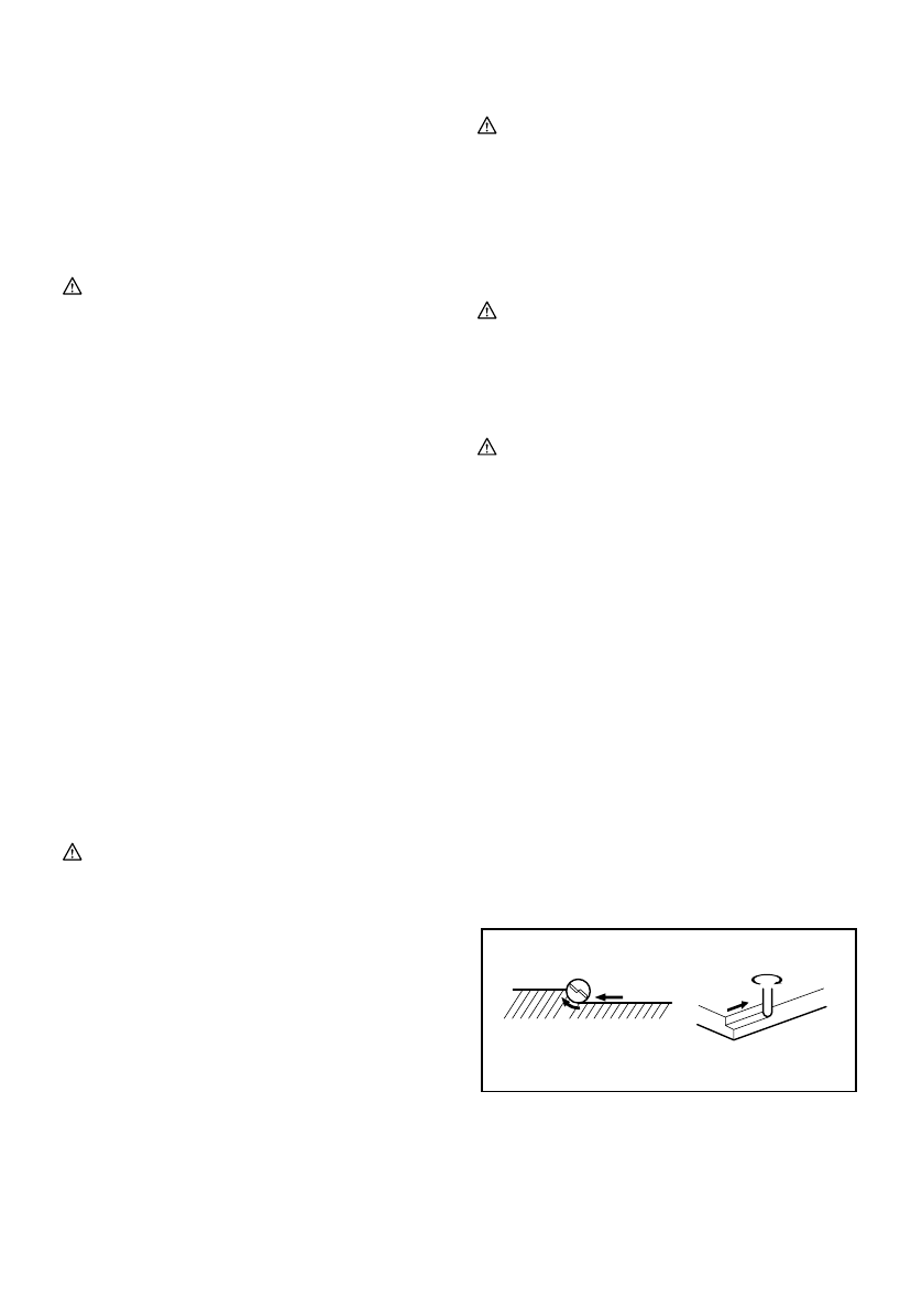
When doing edge cutting, the workpiece surface should
be on the left side of the bit in the feed direction.
1
2
3
4
4
2
001984
1. Workpiece
2. Bit revolving direction
3. View from the top of the tool
4. Feed direction
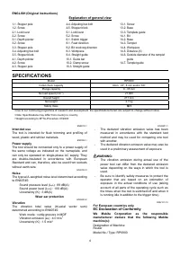
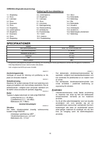
Характеристики

Остались вопросы?Не нашли свой ответ в руководстве или возникли другие проблемы? Задайте свой вопрос в форме ниже с подробным описанием вашей ситуации, чтобы другие люди и специалисты смогли дать на него ответ. Если вы знаете как решить проблему другого человека, пожалуйста, подскажите ему :)


