Дрели P.I.T. PSB16-C - инструкция пользователя по применению, эксплуатации и установке на русском языке. Мы надеемся, она поможет вам решить возникшие у вас вопросы при эксплуатации техники.
Если остались вопросы, задайте их в комментариях после инструкции.
"Загружаем инструкцию", означает, что нужно подождать пока файл загрузится и можно будет его читать онлайн. Некоторые инструкции очень большие и время их появления зависит от вашей скорости интернета.

Impact Drill
9
cessory to become distorted.
► Tighten the cams of gear rim chuck
1
with
drill chuck key
11
applying a similar torque
to each of the three openings on the side
surface of the chuck.
Mounting / dismounting of the drill chuck
(see fi g. 5-6)
► To mount the gear rim chuck
1
, carry out
the operations in consecutive stages as it
is shown in fi gure 5.
► To dismount the gear rim chuck
1
, carry
out the operations in consecutive stages
as it is shown in fi gure 6.
Attention: keep in mind that in the
process of mounting/ dismounting
of the drill chuck the screw 12 has
a left-hand thread.
Screwdriver bit / magnetic holder
(
see
fi g.7
)
When using the power tool as a screwdriver,
use magnetic holder
14
for reliable locking of
screwdriver bits
13
(see fig. 7). A magnetic
holder
14
is not needed for extended screw-
driver bits
13
(specially purposed for screw-
drivers).
Initial operating of the power tool
Always use the correct supply voltage: the
power supply voltage must match the infor-
mation quoted on the power tool identifi cation
plate.
Switching the power tool on/ off
Short-term switching on / off
To switch on, press and hold on/ off switch 9,
to switch off - release it.
Long-term switching on / off
Switching on:
Push on / off switch
9
and lock it in the posi-
tion with lock-on button
10.
Switching off :
Push and release on / off switch
9.
Design features of the power tool
“Impact/ drill” switch
Switch
5
is purposed for switching between
the following operation modes of the power
tool:
►
drilling, screwing, unscrewing
- drilling
without impact in wood, synthetic materi-
als, metal. Screwing and unscrewing fas-
tening components;
►
impact drilling
- impact drilling in brick,
concrete, natural stone.
Drilling, screwing, unscrewing:
To switch to this operation mode,
turn switch
5
so that the drilling sign
coincides with the mark on the body.
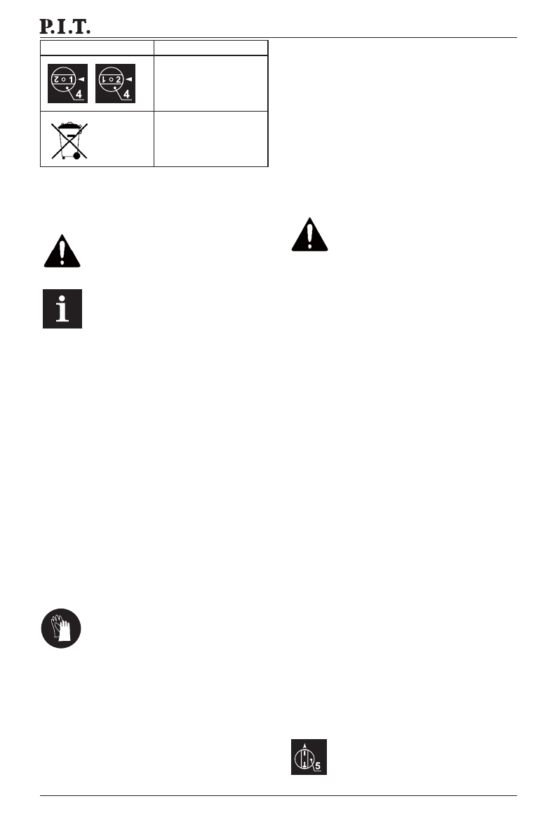
Symbol
Meaning
Step speed controller
position
Do not dispose of
the power tool in
a domestic waste
container
Installation and regulation of pow-
er tool elements
Before carrying out any works on the power
tool it must be disconnected from the mains.
Do not draw up the fastening el-
ements too tight to avoid damag-
ing the thread.
Mounting / dismounting / set-
ting-up of some elements is the
same for all power tool models, in
this case specifi c models are not
indicated in the illustration.
Additional handle (see fi g. 1)
Always use the additional handle
2
when op-
erating. Additional handle
2
may be positioned
as deemed comfortable by the user.
► Loose additional handle
2
as shown in fi g.
1.1.
► Place additional handle
2
in desired posi-
tion (see fi g. 1.2).
► Tighten additional handle
2
as shown in
fi g. 1.3.
Depth stop (see fi g. 2-3)
► Use depth stop
3
to set a required drilling
depth (see fi g. 2-3). Loose additional han-
dle
2
as shown in fi g. 2.1.
► Move depth stop
3
to set a required drilling
depth (see fi g. 3.2).
► Tighten additional handle
2
as shown in
fi g. 2.2, 3.2.
Mounting / replacement of accessories
With long-term use the drill bit
m a y b e c o m e v e r y w a r m ; u s e
gloves to remove it.
Gear rim chuck (see fi g. 4)
► Release the cams grip with drill chuck key
11
, then rotate the quill of gear rim chuck
1
counter-clockwise with your hand (see
fi g. 4) until the cams move apart at the dis-
tance allowing an accessory to be mount-
ed/ replaced.
► Mount / replace an accessory.
► Rotate the quill of gear rim chuck
1
clock-
wise with your hand in order to lock the
accessory mounted. Do not allow the ac-
Характеристики
Остались вопросы?Не нашли свой ответ в руководстве или возникли другие проблемы? Задайте свой вопрос в форме ниже с подробным описанием вашей ситуации, чтобы другие люди и специалисты смогли дать на него ответ. Если вы знаете как решить проблему другого человека, пожалуйста, подскажите ему :)


