
Вытяжки Korting KHC 6972 X - инструкция пользователя по применению, эксплуатации и установке на русском языке. Мы надеемся, она поможет вам решить возникшие у вас вопросы при эксплуатации техники.
Если остались вопросы, задайте их в комментариях после инструкции.
"Загружаем инструкцию", означает, что нужно подождать пока файл загрузится и можно будет его читать онлайн. Некоторые инструкции очень большие и время их появления зависит от вашей скорости интернета.


an omnipolar switch with a minimum contact opening of
3 mm must be placed in between the two; its size must
be suitable for the load required and it must comply with
current legislation.
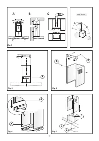
• If the hob is electric, gas, or induction, the minimum distance
between the same and the lower part of the hood must be
at least
65 cm
.
If a connection tube composed of two parts is used, the upper
part must be placed outside the lower part. Do not connect
the cooker hood exhaust to the same conductor used to cir-
culate hot air or for evacuating fumes from other appliances
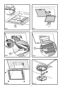
generated by other than an electrical source.Before proceed-
ing with the assembly operations, remove the anti-grease
fi lter(s) (
Fig.7
) so that the unit is easier to handle.
In the case of assembly of the appliance in the suction version
prepare the hole for evacuation of the air.
• Fixing to the wall
- Drill the holes
A
respecting the distances indicated (
Fig.2
). -
Fix the appliance to the wall and align it in horizontal position
to the wall units.
- When the appliance has been adjusted, defi nitely fi x the
hood using the screws
A
(
Fig.5
).
- For the various installations use screws and screw anchors
suited to the type of wall (e.g. reinforced concrete, plaster-
board, etc.).
If the screws and screw anchors are provided with the product,
check that they are suitable for the type of wall on which the
hood is to be fi xed.
• Fixing the decorative telescopic fl ue
- Arrange the electrical power supply within the dimensions
of the decorative fl ue. If your appliance is to be installed in the
ducting version or in the version with external motor, prepare
the air exhaust opening.
- Adjust the width of the support bracket of the upper fl ue
(
Fig.3
).
- Then fi x it to the ceiling using the screws
A
(
Fig.3
) in such a
way that it is in line with your hood and respecting the distance
from the ceiling indicated in
Fig.2
.
- Connect the fl ange
C
to the air exhaust hole using a con-
nection pipe (
Fig.5
).
- Insert the upper fl ue into the lower fl ue.
- Fix the lower fl ue to the hood using the screws
B
provided
(
Fig.5
), extract the upper fl ue up to the bracket and fi x it with
the screws
B
(
Fig.3
).
- If your appliance has the lower connections indicated as in
Fig. 4A
, the fi xing to be carried out is that shown in
Fig. 6A
To transform the hood from a ducting version into a fi ltering
version, ask your dealer for the charcoal fi lters and follow the
installation instructions.
• Filter hood
Please note:
In order to transform the hood from
EXTRACTOR HOOD
into
FILTER HOOD
the carbon fi lters must be ordered at your
distributor as accessory.
We have two different types of Kit, one with extractable carbon
filters (
Fig.8
) and the other one with re-usable carbon filters
(washable). (
Fig.9
)
- To replace the extractable active carbon filters
X
, pull lever
outwards as shown in
Fig.8
- To replace re-usable carbon filters
Y
, remove the brackets
from their seat, pulling them outwards. (
Fig.9
)
If you find a bracket such as the one indicated in
Fig.9a
included in the product packaging, this should be fixed to
the hood using the supplied screws.
USE AND MAINTENANCE
•
We recommend that the cooker hood is switched on before
any food is cooked.
We also recommend that the appliance is left running for
15 minutes after the food is cooked, in order to thoroughly
eliminate all contaminated air.
The eff ective performance of the cooker hood depends on
constant maintenance; the anti-grease fi lter and the active
carbon fi lter both require special attention.
• The anti-grease fi lter
is used to trap any grease particles
suspended in the air, therefore is subject to saturation (the
time it takes for the fi lter to become saturated depends on
the way in which the appliance is used).
- To prevent potential fi re hazards, the anti-grease fi lters should
be washed a minimum of every 2 months (it is possible to use
the dishwasher for this task).
- After a few washes, the colour of the fi lters may change. This
does not mean they have to be replaced.
If the replacement and washing instructions are not followed,
the anti-grease fi lters may present a fi re hazard.
• The active carbon fi lters
are used to purify the air which is
released back into the room.
The fi lters are not washable or re-usable and must be replaced
at least once every four months.
The active carbon fi lter saturation level depends on the fre-
quency with which the appliance is used, the type of cooking
performed and the regularity with which the anti-grease
fi lters are cleaned.
• Clean the cooker hood frequently, both inside and outside,
using a cloth which has been dampened with denatured
alcohol or neutral,
non
-abrasive liquid detergents.
• The light on the cooker hood is designed for use during
cooking and not for general room illumination.
Extended use of the light reduces the average duration of
the bulb.
• Replacing halogen light bulbs
(
Fig. 10
).
To replace the halogen light bulbs
B
, remove the glass panel
C
using a lever action on the relevant cracks.
Replace the bulbs with new ones of the same type.
Caution
: do not touch the light bulb with bare hands.
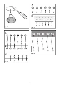
• Replacing halogen light bulbs
(
Fig. 11
).
In order to replace the dichroic lamps, carefully remove
the lamp from the lamp holder with the help of a small fl at
screwdriver or a similar tool.
PLEASE NOTE! In doing this
operation, please take care not to scratch the hood.
Replace the bulbs with new ones of the same type.
• Commands
(
Fig.12
)
- Luminous
(
Fig.12A
)
- Electronic
(
Fig.12B
)
the key symbols are explained below:
A
= LIGHT
B
= OFF
C
= SPEED I
D
= SPEED II
E
= SPEED III
F
= AUTOMATIC STOP TIMER - 15 minutes
(*)
- 7 -
Характеристики

Остались вопросы?Не нашли свой ответ в руководстве или возникли другие проблемы? Задайте свой вопрос в форме ниже с подробным описанием вашей ситуации, чтобы другие люди и специалисты смогли дать на него ответ. Если вы знаете как решить проблему другого человека, пожалуйста, подскажите ему :)


