
Вытяжки Jet Air Round An Gold A/60 - инструкция пользователя по применению, эксплуатации и установке на русском языке. Мы надеемся, она поможет вам решить возникшие у вас вопросы при эксплуатации техники.
Если остались вопросы, задайте их в комментариях после инструкции.
"Загружаем инструкцию", означает, что нужно подождать пока файл загрузится и можно будет его читать онлайн. Некоторые инструкции очень большие и время их появления зависит от вашей скорости интернета.

J78
J78
J78
J78
GB
9
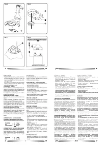
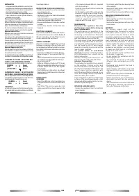
of 2 screws and dowels Ø 8 mm., supplied
w i t h t h e h o o d F i g . 2 .
- Make the chimney with slits run inside the
o t h e r c h i m n e y
- Fix the chimney with slits turned up to the
b r a c k e t " E " u s i n g t h e t w o s c r e w s 2 , 9 x 9 , 5
s u p p l i e d w i t h t h e h o o d ; p u t t h e o t h e r
c h i m n e y o n t h e u p p e r p a r t o f t h e h o o d
a n d f i x i t u s i n g t h e 2 s c r e w s 2 , 9 x 9 , 5
s u p p l i e d w i t h t h e h o o d F i g . 1 .
M A I N T E N A N C E
D i s c o n n e c t t h e a p p l i a n c e f r o m t h e
electrical power supply before doing any
t y p e o f m a i n t e n a n c e .
T h e p e r f o r m a n c e a n d o p e r a t i o n o f t h e
hood depends directly upon the frequency
o f c l e a n i n g a n d m a i n t e n a n c e . T h i s h o l d s
especially true for the aluminum grates (
G
)
a n d t h e a c t i v a t e d c h a r c o a l f i l t e r (
C
) .
T h e g r a t e s e r v e s t o t r a p g r e a s e p a r t i c l e s
and solids suspended in the air. Therefore,
i t i s s u b j e c t t o g e t t i n g c l o g g e d o v e r t i m e ,
a n d t h e s p e e d a t w h i c h i t g e t s c l o g g e d
d e p e n d s o n h o w t h e h o o d i s u s e d a n d t h e
t y p e o f c o o k e r i n s t a l l e d .
T h e
g r a t e s m a d e o f c o l d - d r a w n
a l u m i n u m
s h o u l d b e w a s h e d b y h a n d o r
i n t h e d i s h w a s h e r o n c e a m o n t h . L e t d r y
b e f o r e r e m o u n t i n g .
I f t h e s e c l e a n i n g i n s t r u c t i o n s a r e n o t
f o l l o w e d , i t w i l l r e s u l t i n t h e r i s k o f f i r e .
A c t i v a t e d C h a rc o a l F i l t e r
The activated charcoal filter is only present
o n t h e v e n t l e s s , f i l t e r i n g v e r s i o n a n d
s e r v e s t o t r a p o d o r s a n d c l e a n t h e a i r. T h e
life of the charcoal filter will depend on the
t y p e o f c o o k e r a n d t h e r e g u l a r i t y w i t h
which the grease filters are cleaned. In any
c a s e , t h e c a r t r i d g e m u s t b e r e p l a c e d a t
l e a s t o n c e e v e r y f o u r m o n t h s .
Clean all deposits on the fan and the other
surfaces of the hood frequently with a cloth
dampened with denatured alcohol or non-
a b r a s i v e l i q u i d d e t e r g e n t s .
REPLACING HALOGEN LAMPS
- Unplug the appliance from the electrical
power supply;
- For removal, extract the glass-bearing frame
of the spotlight.
- Replace the faulty lamps, using only 20 W
(max) halogen lamps;
- Remount the chrome-plated diffuser rings.
REPLACING INCANDESCENT LAMPS
40W (E14) max
- Disconnect the hood from the electricity
- Remove the grate
- Replace the damaged lamp with one of the
same power.
WA R N I N G
T h e c o o k i n g v a p o r s m u s t n o t b e
d i s c h a r g e d i n t o a f l u e u s e d f o r v e n t i n g
c o m b u s t i o n f u m e s o r g a s e s , n o r i n t o a
d u c t u s e d a s a f l u e f o r r o o m s i n w h i c h
o p e n f l a m e a p p l i a n c e s a r e i n s t a l l e d . T h e
installation for the discharge of the vapors
m u s t c o m p l y w i t h a l l l o c a l a n d n a t i o n a l
c o d e s a n d s a f e t y s t a n d a r d s . I f t h e h o o d
i s b e i n g u s e d i n t h e o u t d o o r v e n t e d m o d e
w h e r e o t h e r v e n t e d f u e l - b u r n i n g
a p p l i a n c e s a r e i n s t a l l e d , y o u m u s t c h e c k
t o m a k e s u r e t h a t t h e r e i s a s u f f i c i e n t
s u p p l y o f a i r t o t h e r o o m .
- D o n o t a t t e m p t t o c h e c k t h e f i l t e r s w h i l e
t h e h o o d i s i n o p e r a t i o n .
- D o n o t o b s t r u c t t h e v e n t i l a t i o n s l o t s f o r
d i s c h a r g i n g t h e a i r.
- D o n o t t o u c h t h e l a m p s o r t h e l a m p
d i f f u s e r s a f t e r p r o l o n g e d u s e o f t h e
h o o d .
- F l a m b é i n g f o o d b e n e a t h t h e h o o d i s
s t r i c t l y p r o h i b i t e d .
- Av o i d u s i n g a n o p e n f l a m e , a s i t c o u l d
d a m a g e t h e f i l t e r s a n d i n c r e a s e t h e r i s k
o f f i r e .
- N e v e r l e a v e f r y i n g f o o d u n a t t e n d e d t o
p r e v e n t h o t o i l f r o m c a t c h i n g f i r e .
- B e f o r e p e r f o r m i n g a n y m a i n t e n a n c e ,
d i s c o n n e c t t h e h o o d f r o m t h e e l e c t r i c a l
m a i n s .
- T h e m a n u f a c t u r e r w i l l n o t b e h e l d l i a b l e
f o r d a m a g e s c a u s e d b y t h e f a i l u r e t o
f o l l o w t h e f o r e g o i n g i n s t r u c t i o n s .
F
12
INSTALLATION
- Cet appareil doit être installé à au moins 65 cm
au-dessus d’un plan de cuisson équipé de foyers
électriques et à au moins 65 cm au-dessus d’un
plan équipé de foyers à gaz ou mixtes.
- Si la notice d’installation de l’appareil de cuisson
à gaz préconise une plus grande distance,
veuillez en tenir compte.
Raccordement électrique
Avant d’effectuer le moindre raccordement, con-
trôlez si la tension de réseau correspond bien à
la tension indiquée sur l’étiquette des caractéris-
tiques située à l’intérieur de l’appareil.
Pour le raccordement électrique, nous vous con-
seillons de faire appel à un technicien qualifié.
Appareil doté de fiche
Branchez-le à une prise conforme aux normes
appliquées en la matière.
Une fois qu’elle a été insérée dans la prise, la
fiche doit pouvoir être facilement accessible.
Si vous désirez le brancher directement à la li-
gne électrique, enlevez la fiche et montez un in-
terrupteur bipolaire conforme avec au moins 3
mm d’ouverture entre les contacts.
Appareil dépourvu de fiche
Montez une fiche conforme ou bien un interrup-
teur bipolaire conforme avec au moins 3 mm
d’ouverture entre les contacts.
Nous déclinons toute responsabilité en cas d’inconvé-
nients dus à l’inobservation de la disposition susdite.
L’APPAREIL EN CLASSE 1 DOIT ETRE RAC-
CORDE A UNE INSTALLATION DE TERRE
Le branchement doit être réalisé comme suit :
MARRON
=
L
(ligne)
BLEU
=
N
(neutre)
JAUNE/VERT =
(terre)
L’APPAREIL EN CLASSE 2 NE DOIT PAS ETRE
RACCORDE A UNE INSTALLATION DE TERRE
Pour les appareils en classe 2, dont l’étiquette des
caractéristiques porte le symbole d’un double carré,
procédez au branchement comme suit :
MARRON =
L
(ligne)
BLEU
=
N
(neutre)
UTILISATION
La hotte est conçue pour fonctionnement en ver-
sion aspirante à évacuation extérieure ou filtrante
à recyclage intérieur.
I N S T R U C T I O N P O U R L E M O N TA G E F I G . 6
- Positionnez le gabarit au centre et procédez
aux perçages voulus.
- Fixez les chevilles au mur
- Introduisez 2 vis dans les trous intermédiaires
sans visser à fond
- Suspendez la hotte aux deux vis à travers les fentes
prévues dans sa partie arrière et serrez-les
- Bloquez-la définitivement à l’aide des vis et des
rondelles
- Les vis et les chevilles sont fournies avec
l’appareil
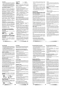
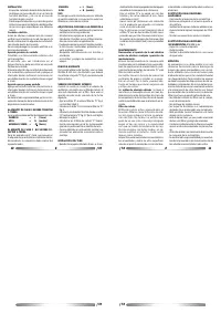
F O N C T I O N A S P I R A N T E
Pour avoir la possibilité de utiliser cette fonction,
Vous devez Vous procurer une tube flexible Ø
120 mm. à joindre au raccord "F" Fig.3, qui, par
la suite, devra etre fixè au plafond.
V E R S I O N F I LT R A N T E
Quand on n'a pas la possibilité d'evacuer l'air à
l'extérieur, on employe un filtre au charbon actif.
L'air est depuré par le filtre et remis dans le milieu.
Pour utiliser la hotte dans cette version, procéder
comme suit:
- Fixer le raccord filtrant "D" à l'ètrier "E" Fig.2.
- Insèrer la bague "A" sur le raccord filtrant "D"
Fig.2.
- Insèrer un tube flexible du raccord "F" à la bague
"A" et le fixer avec des petites bandes Fig.3.
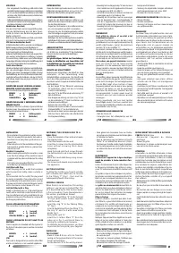
- Démontez la grille “G”
- Enfilez les 2 filtres au charbon actif “C” par les
côtés comme illustré fig.5 et fixez-les en tournant
le bouton central dans le sens des aiguilles
d’une montre.
- Pour l'utilisation en cette version, Vous devez
Vous procurer le matèriel pour le montage chez
Votre fournisseur.
I N S TA L L AT I O N
CHEMINEE
- Faire 2 trous Ø 8 mm. à 4 cm. du plafond, sur
la perpendiculaire au trou d'èvacuation de la
hotte.
- Fixer l'ètrier "E" au mur au moyen des 2 vis
et des goujons Ø 8 mm. fournis avec la hotte
Fig.2.
Характеристики

Остались вопросы?Не нашли свой ответ в руководстве или возникли другие проблемы? Задайте свой вопрос в форме ниже с подробным описанием вашей ситуации, чтобы другие люди и специалисты смогли дать на него ответ. Если вы знаете как решить проблему другого человека, пожалуйста, подскажите ему :)


