
Вытяжки Falmec Stella isola 90 - инструкция пользователя по применению, эксплуатации и установке на русском языке. Мы надеемся, она поможет вам решить возникшие у вас вопросы при эксплуатации техники.
Если остались вопросы, задайте их в комментариях после инструкции.
"Загружаем инструкцию", означает, что нужно подождать пока файл загрузится и можно будет его читать онлайн. Некоторые инструкции очень большие и время их появления зависит от вашей скорости интернета.

29
ENGLISH
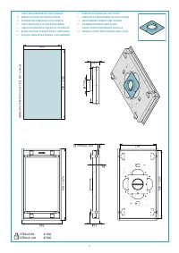
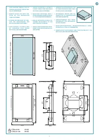
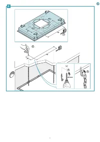
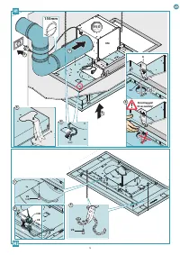
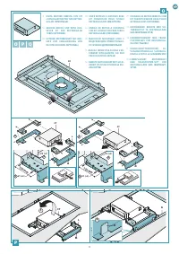
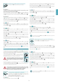
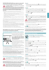
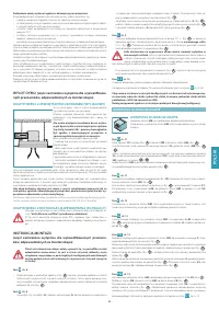
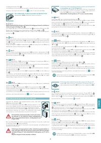
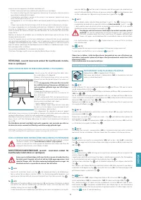
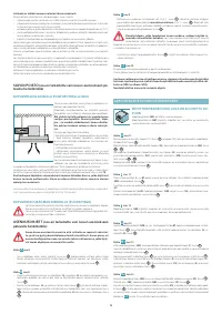
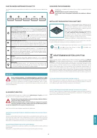
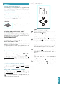
MOTOR UNIT (SLIM) PLACED ON THE HOOD
The motor unit (
SLIM
) is connected directly to the hood.
Phase
The motor unit (SLIM) can also be installed on the hood in various positions in order
to have the desired air outlet direction (Fig.
2
)
Remove the lange (
FC
) assembled on the hood (Fig.
1
) and the knockouts (
ST
) relating
to the deined assembly position of the motor unit (
SLIM
) (Fig.
2
). Assemble the plug
(
TC SLIM
) on the hood, always bear in mind the selected assembly coniguration (Fig.
3
).
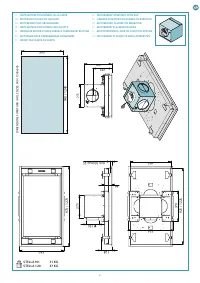
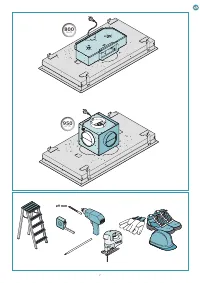
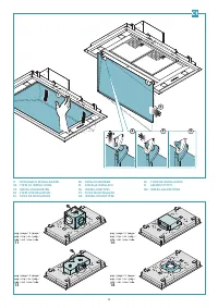
Phase
Check the correct position between the elements (
L
) and (
M
), which form the motor unit
(
SLIM
) support brackets in relation to the deined assembly position (Fig.
1
). If required,
position them at the height indicated in (Fig.
2
) and secure them with 8 screws (
V1
).
Secure the support brackets (
L+M
) to the motor unit (
SLIM
) using the 4 screws (
V2
), taking the
desired air outlet direction into consideration (Fig.
3
).
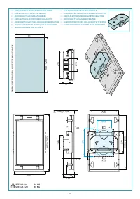
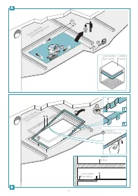
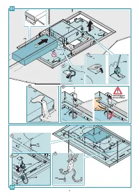
Phase
page 15
Place the assembly composed of the motor unit (
SLIM
) and its supports (
L+M
) on the false
ceiling (Fig.
1
), taking care to centre the assembly by means of the laps (
H
) of the protec-
tion template (
G
) (Fig.
2
).
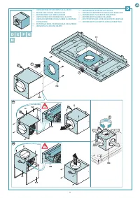
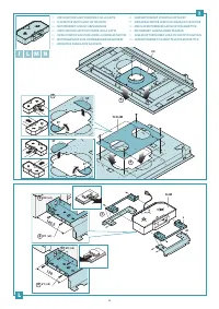
Phase
Connect the air outlet itting of the motor unit (
SLIM
) to the pipe (
FR
) set up for external
discharge (Fig.
1
).
Set up the electric connection to power the hood only after having disconnected the main
power supply switch and complied with current regulations (Fig.
2
).
Lift the hood towards the false ceiling (Fig.
3
) and pass the chains through the safety holes
of the hood (Fig.
4
).
Lift the knockouts and insert the connector (
CM
) from the motor unit (
SLIM
) into the drilled
hole (Fig.
5
).
Insert the hood in the previously reinforced false ceiling: as the hooks (
G
) open, they provision-
ally support the hood on the false ceiling (Fig.
6
). Tighten all screws (
V3
) in order to open
the hooks (
G
) and block the hood on the false ceiling (Fig.
7
).
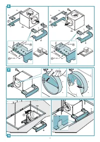
Phase
Fasten the motor unit (
SLIM
) to the hood body using the 4 screws (
V5
) and 4 washers (
V6
)
supplied (Fig.
2
).
Connect the connector (
CM
) of the motor unit (
SLIM
) to the hood connector (
CE
) (Fig.
3
).
Fix the safety chains to the hood using the supplied screws (
V4
) and cut the excess chain
(Fig.
4
). Place back the anti-grease metal ilters removed earlier and then carefully place
back the external suction panel by conducting the steps in phase
C1
on page 10 in reverse
order.
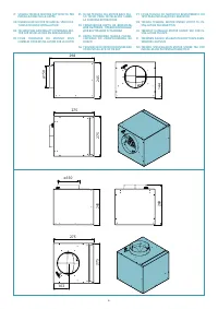
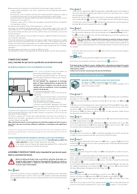
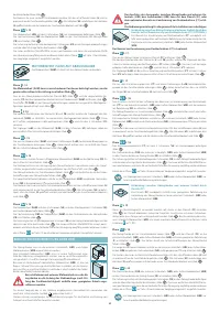
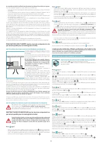
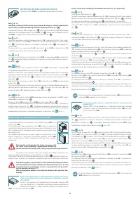
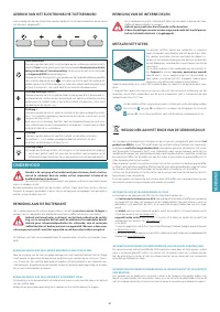
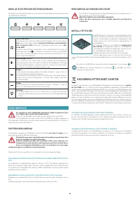
REMOTE MOTOR UNIT (URS OR URE)
The hood can be connected to the under-roof (
URS
) and outdoor (
URE
) remote motor unit .
In the case of an under-roof motor unit (
URS
), it must be placed next to the technical com-
partment inside the home, protected against atmospheric agents and
within reach for any maintenance operations.
In the case of an outdoor motor unit (
URE
), it is recommended to ind a
position protected from rain, snow, wind, etc., in order to prevent rain and
humidity from entering, which can damage the outdoor unit.
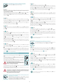
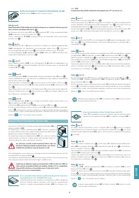
In the case of installation with remote motor, you must
connect the hood to the electrical system earthing (after
having veriied its functioning)
by means of a suitable ca-
ble.
To execute this operation, use the threaded insert set up in the hood
structure and identiied with a label and symbol
.
It is recommended that you comply with the current regulations on electrical safety of sys-
tems and devices regarding earthing equipment.
Connection of the suction pipe between the hood and the under-roof (URS)
or outdoor (URE) remote motor unit can be carried out by means of the
lange
(FC)
or air conveyor kit for rectangular pipes (CT) optional
.
Follow the instructions according to the desired installation.
Connection between the hood and the remote unit by means of the
air conveyor kit for rectangular pipes (CT) (OPTIONAL)
The conveyor kit for rectangular pipes (
CT
) enables connection of the
hood to an under-roof (
URS
) or outdoor (
URE
) remote motor unit by
means of suitable rectangular-section pipes.
The conveyor kit for rectangular pipes (CT) is optional.
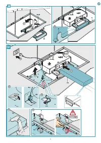
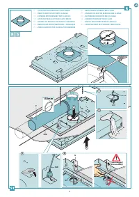
Phase
page 17
Remove the lange (
FC
) assembled on the hood (Fig.
1
).
Check the correct position between the elements (
L
) and (
M
), which form part of the sup-
port brackets of the conveyor kit (
CT
) for rectangular pipes (Fig.
2
). If required, position
them at the height indicated in (Fig.
3
) and secure them with 8 screws (
V1
).
Secure the support brackets (
L+M
) to the conveyor kit for rectangular pipes (
CT
) using the 4
screws (
V2
), taking the desired air outlet direction into consideration (Fig.
4
).
Phase
Place the assembly composed of the conveyor kit (
CT
) and its supports (
L+M
) on the false
ceiling (Fig.
1
), taking care to centre the assembly by means of the laps (
H
) of the protec-
tion template (
G
) (Fig.
2
).
Phase
Connect the kit conveyor air outlet itting for rectangular pipes (
TC
) to the under-roof (
URS
)
or outdoor (
URE
) remote unit with a suitable (
FR
) pipe (Fig.
1
).
Lift the hood towards the false ceiling (Fig.
2
) and pass the chains through the safety holes
of the hood (Fig.
3
).
Lift the knockouts and insert the connector (
CUE
) from the under-roof (
URS
) or outdoor (
URE
)
remote unit into the drilled hole (Fig.
4
).
Insert the hood in the previously reinforced false ceiling: as the hooks (
G
) open, they provision-
ally support the hood on the false ceiling (Fig.
5
). Tighten all screws (
V3
) in order to open
the hooks (
G
) and lock the hood on the false ceiling (Fig.
6
).
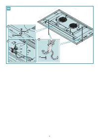
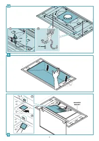
Phase
Fasten the kit conveyor (
CT
) to the hood by means of 8 screws (
V5
) (Fig.
1
).
Connect the (
CUE
) connector of the under-roof (
URS
) or outdoor (
URE
) remote unit to the
hood connector (
CE
) (Fig.
2
).
Fix the safety chains to the hood using the supplied screws (
V4
) and cut the excess chain
(Fig.
3
). Place back the anti-grease metal ilters removed earlier and then carefully place
back the external suction panel by conducting the steps in phase
C1
on page 10 in reverse
order.
To assemble the under-roof (
URS
) or outdoor (
URE
) remote motor unit, refer to the
relative instructions booklet.
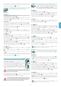
Hood and remote unit connection by means of the lange (FC)
The lange (
FC
), by means of suitable piping, connects the hood to the
under-roof (
URS
) or outdoor (
URE
) remote motor unit.
Phase
Should you wish to use a check valve, assemble it on the lange (
FC
) (Fig.
1
); lock it to the
lange by pushing the laps of the itting downwards with a screwdriver or grippers (Fig.
2
). If the under-roof (
URS
) remote motor unit is used, remove the check valve assembled on it
(refer to the instructions
11
).
Phase
Lift the hood towards the false ceiling (Fig.
1
) and connect the lange (
FC
) to the un-
der-roof (
URS
) or outdoor (
URE
) remote unit with a suitable (
F
) pipe (Fig.
2
). Pass the
chains through the safety holes of the hood (Fig.
3
).
Lift the knockouts and insert the connector (
CUE
) from the under-roof (
URS
) or outdoor (
URE
)
remote unit into the drilled hole (Fig.
4
).
Insert the hood in the previously reinforced false ceiling: as the hooks (
G
) open, they provisional-
ly support the hood on the false ceiling (Fig.
5
). Tighten all screws (
V3
) in order to open the
hooks (
G
) and lock the hood on the false ceiling (Fig.
6
).
Phase
Connect the (
CUE
) connector of the under-roof (
URS
) or outdoor (
URE
) remote unit to the
hood connector (
CE
) (Fig.
1
).
Fix the safety chains to the hood using the supplied screws (
V4
) and cut the excess chain
(Fig.
2
). Place back the anti-grease metal ilters removed earlier and then carefully place
back the external suction panel by conducting the steps in phase
C1
on page 10 in reverse
order.
To assemble the under-roof (
URS
) or outdoor (
URE
) remote motor unit, refer to the
relative instructions booklet.
URS
URE
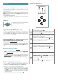
Содержание
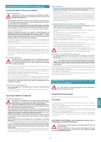
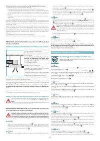
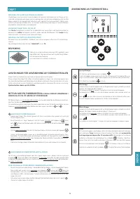
- 47 СИЙ; МЕРЫ ПРЕДОСТОРОЖНОСТИ ДЛЯ УСТАНОВЩИКА; УСТАНОВКА; цированного персонала, занимающегося установкой вытяжки); ТЕХНИЧЕСКИЕ ХАРАКТЕРИСТИКИ
- 48 ОТВОД ДЫМОВ; фицированного персонала, занимающегося установкой вытяжки); ИНСТРУКЦИИ ПО МОНТАЖУ; МОТОРНЫЙ БЛОК, РАЗМЕЩЁННЫЙ НА ВЫТЯЖКЕ
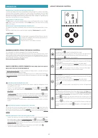
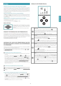
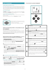
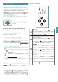
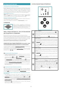
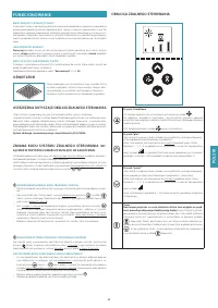
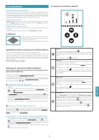
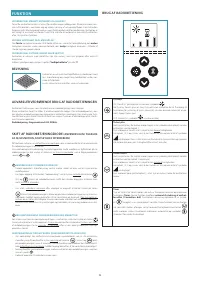
- 50 УНКЦИОНИРОВАНИЕ; ОСВЕЩЕНИЕ; (ИСПОЛЬЗОВАТЬ ТОЛЬКО; ИСПОЛЬЗОВАНИЕ РАДИОУПРАВЛЕНИЯ
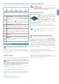
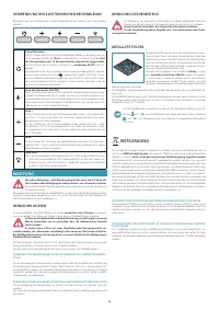
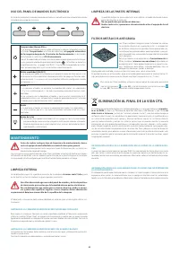
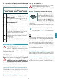
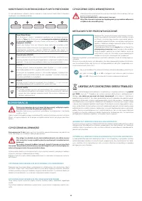
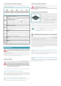
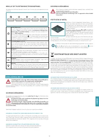
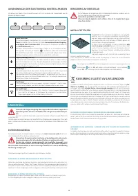
- 51 ИСПОЛЬЗОВАНИЕ ЭЛЕКТРОННОЙ ПАНЕЛИ УПРАВЛЕНИЯ; ТЕХОБСЛУЖИВАНИЕ; НАРУЖНАЯ ЧИСТКА; ОЧИСТКА ВНУТРЕННИХ ЧАСТЕЙ; УТИЛИЗАЦИЯ ПО ЗАВЕРШЕНИИ СРОКА СЛУЖБЫ
Характеристики

Остались вопросы?Не нашли свой ответ в руководстве или возникли другие проблемы? Задайте свой вопрос в форме ниже с подробным описанием вашей ситуации, чтобы другие люди и специалисты смогли дать на него ответ. Если вы знаете как решить проблему другого человека, пожалуйста, подскажите ему :)


