Водонагреватели Ariston TI TRONIC INDUSTRIAL 200-300-500 - инструкция пользователя по применению, эксплуатации и установке на русском языке. Мы надеемся, она поможет вам решить возникшие у вас вопросы при эксплуатации техники.
Если остались вопросы, задайте их в комментариях после инструкции.
"Загружаем инструкцию", означает, что нужно подождать пока файл загрузится и можно будет его читать онлайн. Некоторые инструкции очень большие и время их появления зависит от вашей скорости интернета.

PLANCHES ( F )
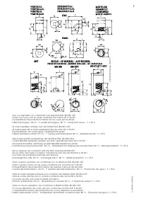
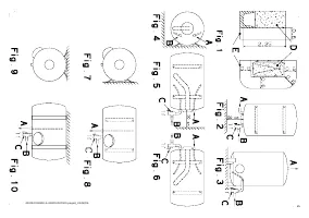
Fig.1
D- volume enveloppe
E- volume de protection
Fig.2, 3 A- eau chaude – bague rouge
B- eau froide – bague bleue
C- groupe de sécurité
Fig.4
modèle horizontal vue latérale
A- eau chaude – bague rouge
B- eau froide – bague bleue
Fig.5
modèle horizontal à droite
A- eau chaude – bague rouge
B- eau froide – bague bleue
C- groupe de sécurité
Fig.6
modèle horizontal à gauche
A- eau chaude – bague rouge
B- eau froide – bague bleue
Fig.7
horizontal tubes sur virole au mur
Fig.8
horizontal tubes sur virole
A- eau chaude – bague rouge
B- eau froide – bague bleue
Fig.9
horizontal tubes sur virole au plafond
Fig.10
horizontal tubes sur virole au plafond
A- eau chaude – bague rouge
B- eau froide – bague bleue
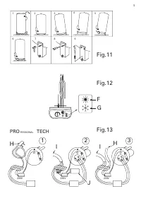
Fig.11
Modèle sur socle, montage des pieds
Fig.12
F- été
G- hiver
Fig.13
H- 230V alimentation permanente
I- 230V – 400V alimentation de nuit
J- accumulateur
AFBEELDINGEN ( NL )
Afb.1
D- omhullende ruimte
E- veiligheidsruimte
Afb.2, 3 A- warm water – rode ring
B- koud water – blauwe ring
C- veiligheidsgroep
Afb.4
horizontaal model zijaanzicht
A- warm water – rode ring
B- koud water – blauwe ring
Afb.5
horizontaal model rechts
A- warm water – rode ring
B- koud water – blauwe ring
C- veiligheidsgroep
Afb.6
horizontaal model links
A- warm water – rode ring
B- koud water – blauwe ring
Afb.7
horizontale buizen op beslag tegen de wand
Afb.8
horizontale buizen op beslag tegen
A- warm water – rode ring
B- koud water – blauwe ring
Afb.9
horizontale buizen op beslag tegen het plafond
Afb.10
horizontale buizen op beslag tegen het plafond
A- warm water – rode ring
B- koud water – blauwe ring
Afb.11
Model op sokkel, montage van de voeten
Afb.12
F- zomer
G- winter
Afb.13
H- 230V permanente voeding
I- 230V – 400V nachtvoeding
J- accumulator
ABBILDUNGEN ( D )
Abb.1
D- Hüllvolumen
E- Schutzvolumen
Abb.2, 3 A- Warmes Wasser – roter Ring
B- Kaltes Wasser – blauer Ring
C- Sicherheitsgruppe
Abb.4
horizontales Modell – seitliche Ansicht
A- Warmes Wasser – roter Ring
B- Kaltes Wasser – blauer Ring
Abb.5
horizontales Modell rechts
A- Warmes Wasser – roter Ring
B- Kaltes Wasser – blauer Ring
C- Sicherheitsgruppe
Abb.6
horizontales Modell links
A- Warmes Wasser – roter Ring
B- Kaltes Wasser – blauer Ring
Abb.7
horizontal – Rohre auf Ring an der Wand
Abb.8
horizontal – Rohre auf Ring an der Wand
A- Warmes Wasser – roter Ring
B- Kaltes Wasser – blauer Ring
Abb.9
horizontal – Rohre auf Ring an der Decke
Abb.10
horizontal – Rohre auf Ring an der Decke
A- Warmes Wasser – roter Ring
B- Kaltes Wasser – blauer Ring
Abb.11
Sockelmodell, Montage der Füße
Abb.12
F- Sommer
G- Winter
Abb.13
H- permanente 230V-Stromversorgung
I- 230V – 400V Nachtstromversorgung
J- Akkumulator
PLATES ( GB )
Fig.1
D- shell volume
E- protection volume
Fig.2, 3 A- hot water – red ring
B- cold water – blue ring
C- safety assembly
Fig.4
horizontal model, side view
A- hot water – red ring
B- cold water – blue ring
Fig.5
horizontal model, right
A- hot water – red ring
B- cold water – blue ring
C- safety assembly
Fig.6
horizontal model, left
A- hot water – red ring
B- cold water – blue ring
Fig.7
horizontal tubes on collar on the wall
Fig.8
horizontal tubes on collar
A- hot water – red ring
B- cold water – blue ring
Fig.9
horizontal tubes on collar on the ceiling
Fig.10
horizontal tubes on collar on the ceiling
A- hot water – red ring
B- cold water – blue ring
Fig.11
Model on base, assembly on legs
Fig.12
F- summer
G- winter
Fig.13
H- 230V continuous supply
I- 230V – 400V night supply
J- accumulator
DIBUJOS ( E )
Fig.1
D- volumen de envoltura
E- volumen de protección
Fig.2, 3 A- agua caliente – anillo rojo
B- agua fría – anillo azul
C- grupo de seguridad
Fig.4
modelo horizontal vista lateral
A- agua caliente – anillo rojo
B- agua fría – anillo azul
Fig.5
modelo horizontal a la derecha
A- agua caliente – anillo rojo
B- agua fría – anillo azul
C- grupo de seguridad
Fig.6
modelo horizontal a la izquierda
A- agua caliente – anillo rojo
B- agua fría – anillo azul
Fig.7
horizontal tubos sobre virola en la pared
Fig.8
horizontal tubos sobre virola
A- agua caliente – anillo rojo
B- agua fría – anillo azul
Fig.9
horizontal tubos sobre virola en el techo
Fig.10
horizontal tubos sobre virola en el techo
A- agua caliente – anillo rojo
B- agua fría – anillo azul
Fig.11
Modelo sobre zócalo,
Montaje sobre patas
Fig.12
F- verano
G- invierno
Fig.13
H- 230V alimentación permanente
I- 230V – 400V alimentación nocturna
J- acumulador
TAVOLE ( I )
Fig.1
D- volume del rivestimento
E- volume di protezione
Fig.2, 3 A- acqua calda – anello rosso
B- acqua fredda – anello blu
C- gruppo di sicurezza
Fig.4
modello orizzontale – vista laterale
A- acqua calda – anello rosso
B- acqua fredda – anello blu
Fig.5
modello orizzontale a destra
A- acqua calda – anello rosso
B- acqua fredda – anello blu
C- gruppo di sicurezza
Fig.6
modello orizzontale a sinistra
A- acqua calda – anello rosso
B- acqua fredda – anello blu
Fig.7
tubi orizzontali su ghiera a muro
Fig.8
tubi orizzontali su ghiera
A- acqua calda – anello rosso
B- acqua fredda – anello blu
Fig.9
tubi orizzontali su ghiera a soffitto
Fig.10
tubi orizzontali su ghiera a soffitto
A- acqua calda – anello rosso
B- acqua fredda – anello blu
Fig.11
Modello su piedistallo
Montaggio dei piedini
Fig.12
F- estate
G- inverno
Fig.13
H- 230V alimentazione continua
I- 230V – 400V alimentazione notturna
J- accumulatore
DESENHOS ( P )
Fig.1
A- volume do invólucro
B- volume de protecção
Fig.2, 3 A- água quente – anel vermelho
B- água fria – anel azul
C- grupo de segurança
Fig.4
modelo horizontal - vista lateral
A- água quente – anel vermelho
B- água fria – anel azul
Fig.5
modelo horizontal à direita
A- água quente – anel vermelho
B- água fria – anel azul
C- grupo de segurança
Fig.6
modelo horizontal à esquerda
A- água quente – anel vermelho
B- água fria – anel azul
Fig.7
horizontal - tubos com virola na parede
Fig.8
horizontal - tubos com virola
A- água quente – anel vermelho
B- água fria – anel azul
Fig.9
horizontal - tubos com virola no tecto
Fig.10
horizontal - tubos com virola no tecto
A- água quente – anel vermelho
B- água fria – anel azul
Fig.10
horizontal - tubos com virola no tecto
A- água quente – anel vermelho
B- água fria – anel azul
Fig.11
Modelo assente no suporte
Montagem dos pés
Fig.12
F- Verão
G- Inverno
Fig.13
H- 230V alimentação permanente
I- 230V – 400V alimentação nocturna
J- acumulador
6


