
Триммеры AL-KO BC 225 B 113253 - инструкция пользователя по применению, эксплуатации и установке на русском языке. Мы надеемся, она поможет вам решить возникшие у вас вопросы при эксплуатации техники.
Если остались вопросы, задайте их в комментариях после инструкции.
"Загружаем инструкцию", означает, что нужно подождать пока файл загрузится и можно будет его читать онлайн. Некоторые инструкции очень большие и время их появления зависит от вашей скорости интернета.


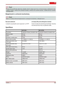


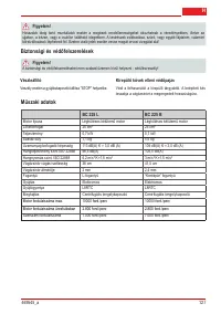


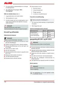


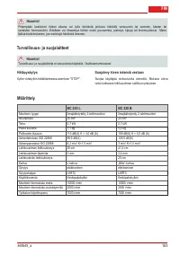


Translation of the original operating instructions
20
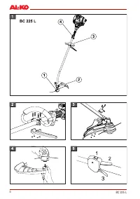
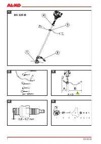
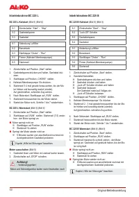
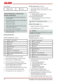
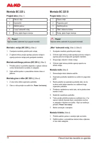
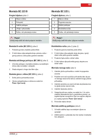
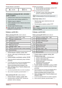
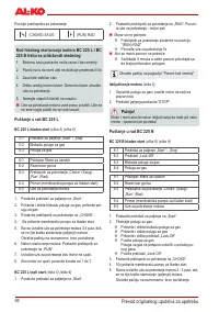
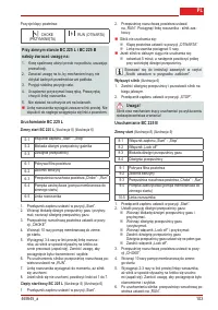
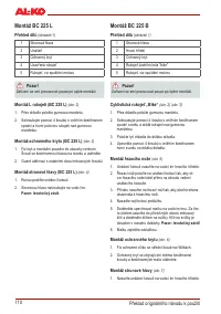
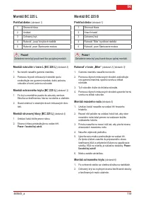
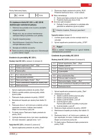
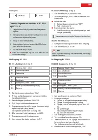
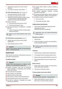
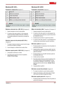
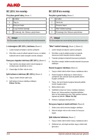
BC 225 B assembly
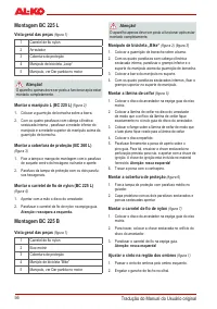
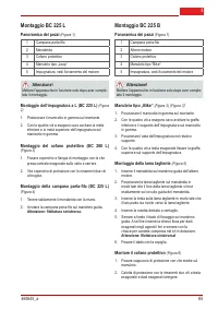
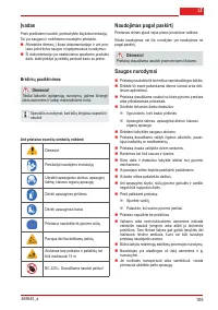
Parts overview
(Fig. 1)
1
String head
2
Drive shaft
3
Guard
4
“Bike” grip
5
Lever, see Starting the engine
Caution!
The machine must not be operated before assembly
work has been completed.
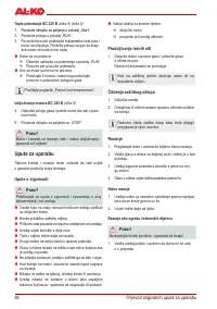
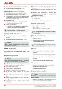
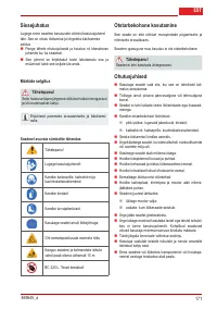
„Bike“ grip
(Fig. 2) (Fig. 3
)
1. Place the rubber sleeve over the support bar.
2. Screw together the lower brace and the grip holder
over the rubber sleeve using the four Allen screws.
3. Place the grip rod into the grip holder.
4. Fasten the upper brace onto the grip holder using the
four Allen screws.
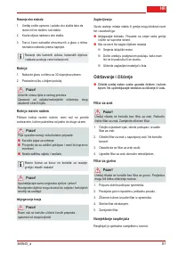
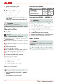
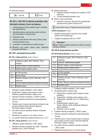
Mounting the cutting blade
(Fig. 5)
1. Place the drive plate onto the guide pin on the drive
shaft.
2. Place the cutting blade onto the drive plate so that the
hole in the cutting blade is positioned precisely on the
guide circle on the drive plate.
3.
Push the flange onto the cutting blade so that the flat
side faces the cutting blade.
4. Fit the fan washer.
5. Secure the clamping nut onto the guide pin. To do
this, insert the Allen key into the relevant holes and
tighten using the spark plug wrench provided.
Cauti-
on: left-hand thread!
6. Secure the nut with the cotter pin.
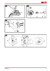
Mounting the guard
(Fig. 6)
1. Fix protection cap with medium screw on the hand-
lebar.
2. Protective cover with the remaining two hex screws
and hex nuts tighten.
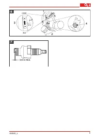
Mounting the string head
(Fig. 7)
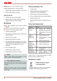
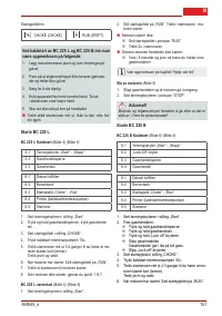
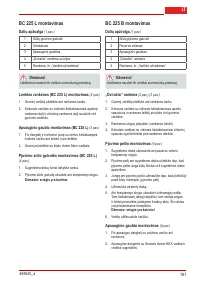
BC 225 L assembly
Parts overview
(Fig. 1)
1
String head
2
Driver
3
Guard
4
„Bike“ grip
5
Lever, see Starting the engine
Caution!
The machine must not be operated before assembly
work has been completed.
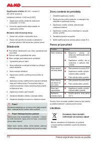
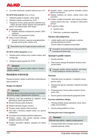
Mounting the L grip (BC 225 L)
(Fig. 2)
1. Place the rubber sleeve over the support bar.
2. Screw together the lower half of the grip and the top
half above the rubber sleeve using the four Allen
screws.
Mounting the guard (BC 225 L)
(Fig. 3)
1. Fix cover and mounting sleeve with the center hexa-
gon socket screw on the stem and tighten.
2. Screw protection cover with the remaining two hexa-
gon socket screws
Mounting the string head (BC 225 L)
(Fig. 4)
1. Hold the driver disc with your hand.
2. Screw the string head onto the guide pin.
Caution: Left-hand thread.


