
Телевизоры GAZER TV40-FS2G - инструкция пользователя по применению, эксплуатации и установке на русском языке. Мы надеемся, она поможет вам решить возникшие у вас вопросы при эксплуатации техники.
Если остались вопросы, задайте их в комментариях после инструкции.
"Загружаем инструкцию", означает, что нужно подождать пока файл загрузится и можно будет его читать онлайн. Некоторые инструкции очень большие и время их появления зависит от вашей скорости интернета.


5
EN
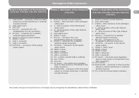
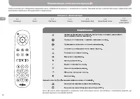
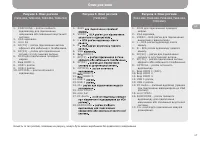
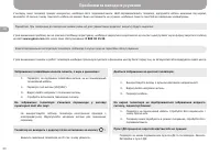
Picture 3. Description of the Connectors
(TV43-FS2)
1. RJ45
to connect a wired network.
2. VIDEO
– RCA connector of the analogue
video input.
3. L
– RCA connector of the left channel
audio input.
4. R
– RCA connector of the right channel
audio input.
5. VGA
video input.
6. HDMI 1
input.
7. RF(T2)
– connector for a TV
broadcasting antenna connection.
8. RF(S2)
- connector for a satellite
antenna signal connection.
9. OPTICAL
– connector of the optical
audio output.
10. HDMI 2
input.
11. HDMI 3
input.
12. USB 2
connector.
13. USB 1
connector.
14. CI+
a slot to connect add-in modules
15. mini YPbPr
.
16. mini AV
.
17. PC Audio
– line audio input (operates
when a video source is connected to the
VGA connector).
18. EARPHONE
– connector of the line audio
output to connect earphones or external
acoustic devices.
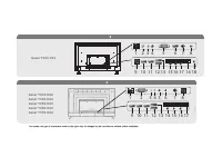
Description of the Connectors
Picture 4. Description of the Connectors
(TV43-US2, TV49-US2, TV55-US2, TV65-US2,
TV70-US2)
1. RJ45
to connect a wired network.
2. VGA
video input.
3. VIDEO
– RCA connector of the analogue
video input.
4. L
– RCA connector of the left channel
audio input.
5. R
– RCA connector of the right channel
audio input.
6. RF(S2)
– connector for a satellite
antenna signal connection.
7. RF(T2)
– connector for a TV
broadcasting antenna connection.
8. OPTICAL
– connector of the optical
audio output.
9. HDMI 1 (ARC)
input.
10. HDMI 2
input.
11. HDMI 3
input.
12. USB 1
connector.
13. USB 2
connector.
14. PC Audio
– line audio input (operates
when a video source is connected to the
VGA connector).
15. mini YPbPr
.
16. EARPHONE
– connector of the line audio
output to connect earphones or external
acoustic devices.
17. CI+
a slot to connect add-in modules.
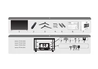
Picture 2. Description of the Connectors
(TV24-HS2, TV32-HS2, TV32-FS2, TV40-FS2)
1. EARPHONE
– connector of the line audio
output to connect earphones or external
acoustic devices.
2. VGA
video input.
3. mini AV
.
4. RF(T2)
– connector for a TV
broadcasting mini AV connection.
5. RF(S2)
– connector for a satellite
antenna signal connection.
6. RJ45
to connect a wired network.
7. HDMI 1
input.
8. USB 1
connector.
9. USB 2
connector.
10. OPTICAL
– connector of the optical
audio output.
The number and type of connectors shown in the figure may be changed by the manufacturer without further notification


