
Смесители Smeg MF9-CR - инструкция пользователя по применению, эксплуатации и установке на русском языке. Мы надеемся, она поможет вам решить возникшие у вас вопросы при эксплуатации техники.
Если остались вопросы, задайте их в комментариях после инструкции.
"Загружаем инструкцию", означает, что нужно подождать пока файл загрузится и можно будет его читать онлайн. Некоторые инструкции очень большие и время их появления зависит от вашей скорости интернета.
ISTRUZIONI DI MONTAGGIO, D’USO E MANUTENZIONE
- Prima dell’installazione e messa in funzione.
Attenzione!
I tubi d’alimentazione devono essere sciacquati con cura prima dell’installazione del miscelatore, in modo che non rimangano trucioli,
residui di saldatura o canapa, o altre impurità all’interno dei tubi. Attraverso tubazioni non sciacquate a fondo o attraverso la rete idrica generale, nel
miscelatore possono entrare corpi estranei in grado di danneggiare le guarnizioni/guarnizioni ad anello. Generalmente si consiglia di installare un filtro
sul raccordo principale dell’acqua. Prima della messa in funzione, svitare l’aeratore e sciacquare molto bene.
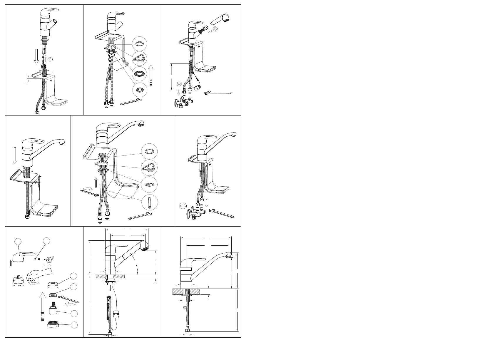
- Montaggio del miscelatore
Fig. 1
- Prima di inserire il monocomando nel foro del lavello assicurarsi che la guarnizione di base sia ben posizionata nella propria sede e che i
flessibili di alimentazione siano ben avvitati al corpo del rubinetto. Sistemare il monocomando sul foro del lavello orientando la bocca di erogazione
verso la vasca del lavello.
Fig. 2 -
Inserire quindi il kit di fissaggio nella sequenza indicata e rispettivamente:
· la guarnizione sagomata e la flangia nel caso si installi il monocomando su un lavello di spessore 3-4 cm;
· la guarnizione sagomata, la flangia triangolare in plastica e la flangia nel caso si installi il monocomando su un lavello in acciaio inox di spessore
1-2 mm.
Serrare a fondo l’apposito tirante o dado filettato.
Nel caso il rubinetto sia un monocomando con doccetta estraibile collegare il flessibile al tubetto di uscita interponendo la guarnizione di tenuta.
Fig. 3
- Procedere al collegamento dei flessibili alla rete di alimentazione. Nel caso il rubinetto sia un monocomando con doccetta estraibile avvitare
la doccetta al tubo flessibile interponendo la guarnizione di tenuta, Fissare il contrappeso di piombo sul tubo del flessibile ad una distanza di 40 cm
dall’attacco del tubetto di uscita e verificare che il flessibile scorra in maniera lineare.
- Sostituzione della cartuccia
Fig. 4 -
Prima di sostituire la cartuccia, accertarsi che il raccordo dell’acqua sia chiuso. Svitare la vite di fissaggio (A) utilizzando una chiave a bru-
gola, estrarre quindi la maniglia (B) sfilandola dalla cartuccia (E). Sollevare la ghiera copricartuccia (C). Svitare la ghiera di fissaggio (D) e togliere la
cartuccia (E) dal corpo del miscelatore (F). Infine introdurre la nuova cartuccia, accertandosi che le due spine di centraggio siano nella loro sede e
che le guarnizioni siano correttamente posizionate.
ASSEMBLING AND MAINTENANCE INSTRUCTIONS
- Before installation and setting to work
Attention!
The feeding pipes have to be rinsed thoroughly before the installation of the mixer, so that no shavings, welding or hemp residual or
other dirt can be found in the pipes. Foreign bodies can enter the mixer through the rinsed pipes or the general water plant and could damage the
washers/ring washers. Normally, it is recommended to install a filter on the main water union. Before the setting to work, unscrew the aerator and
rinse it very well.
- Taps assembling
Fig. 1
- Before inserting the single lever group in the hole of the sink, make sure that the base gasket is properly positioned in its seat and that the
flexible hoses are well tightened to the body of the tap. Place the single lever group in the hole of the sink, orienting the spout toward the sink tank.
Fig. 2 -
Insert the fixing kit with the indicated sequence, and respectively:
· the shaped gasket and flange in case the single lever group is installed on a sink having thickness of 3-4 cm;
· the shaped gasket, the triangular plastic flange and the flange in case of a stainless steel sink having thickness of 1-2 mm.
Tighten well the tie rod or the threaded nut. In case the tap is a single lever group with extractable shower, connect the flexible hose to the outlet pipe
interposing the gasket.
Fig. 3 -
Proceed connecting the flexible hoses to the plumbing. In case the tap is a single lever group with extractable shower, tighten the shower to
the hose interposing the gasket, fix the lead counterweight to the flexible hose at a distance of approx. 40 cm from the connection to the outlet pipe
and confirm the hose can slide smoothly through the passage hole.
- Cartridge replacement
Fig. 4
- Before carrying out this operation make sure that water connection is closed. Unscrew the fastening screw (A) using an Allen wrench, take out
the handle (B), removing it from the cartridge (E). Lift the finishing ring nut (C). Unscrew the fixing ring nut (D) and take the cartridge (E) out form the
mixer body (F). Then put the new cartridge, verifying that the two centering pins enter into the respective seats and that gaskets are well positioned.
INSTRUCTIONS POUR LE MONTAGE ET L’ENTRETIEN
- Avant l’installation et la mise en fonction
Attention!
Les tubes d’alimentation doivent être rincés avec soin avant l’installation du mélangeur, de façon qu’il ne reste pas de riblons, de restes
de soudure ou de chanvre, ou d’autres saletés à l’intérieur des tubes. A travers les tuyauteries qui ne sont pas bien rincées ou à travers l’installation
hydrique générale, des corps étrangers peuvent entrer dans le mélangeur et abîmer les joints/ les joints à anneau. Généralement nous conseillons
d’installer un filtre sur le joint principal de l’eau. Avant la mise en fonction, dévisser l’aérateur et bien rincer.
- Montage des robinets
Fig. 1 -
Avant d’insérer le monocommande dans le trou de l’évier, il faut s’assurer que le joint de base est bien placé dans son emplacement et que
les flexibles d’alimentation sont bien vissés au corps du robinet. Il faut placer le monocommande sur le trou de l’évier en orientant la bouche de
distribution vers le bac de l’évier.
Fig. 2 -
Insérer donc le kit de fixage dans la séquence indiquée et respectivement:
· le joint façonné et la bride si on installe le monocommande sur un évier d’une épaisseur de 3-4 cm;
· le joint façonné, la bride triangulaire en plastique et la bride dans le cas d’un évier en acier inox d’une épaisseur de 1-2 mm.
Serrer à fond le tirant ou l’écrou fileté. Si le robinet est un monocommande avec la douchette détachable, il faut relier le flexible au tuyau de sortie
en interposant le joint d’étanchéité.
Fig. 3 -
Procéder à la liaison des flexibles au réseau d’alimentation. Si le robinet est un monocommande avec la douchette détachable, il faut visser
la douchette au tuyau flexible en interposant le joint d’étanchéité, il faut fixer le contrepoids de plomb sur le tuyau du flexible à une distance de 40 cm
du raccord du tuyau de sortie et il faut vérifier que le flexible glisse de façon linéaire.
- Remplacement de la cartouche
Fig. 4
- Avant d’effectuer la substitution de la cartouche, vérifier que la connexion de l’eau est fermée. Dévisser la vis de fixation (A) utilisant une clé à
griffe, extraire en suite la poignée (B) en la soulevant de la cartouche (E). Soulever la virole de finition (C). Dévisser la virole de fixation (D) et enlever
la cartouche (E) du corps de mitigeur (F). Introduire enfin la cartouche nouvelle, en vérifiant que les deux pivots de centrage entrent dans les sièges
respectifs et que les garnitures sont bien positionnées.
MONTAGE-,WARTUNGS- UND GEBRAUCHSANWEISUNGEN
- Vor der Installation und Inbetriebnahme
Achtung!
Die Zuleitungsrohre müssen vor dem Installieren der Armatur gründlich durchgespült werden, damit keine Späne, Löt - Hanfreste oder
andere Unreinheiten zurückbleiben. Bei nicht durchgespülten Rohrleitungen oder durch die Wasseranlage allgemein können Fremdkörper in die
Armatur geraten und die Dichtungsscheiben/Dichtungen beschädigen. Grundsätzlich empfiehlt sich die Installation eines Filters am Hauptwasseran-
schluß. Vor Inbetriebnahme der Armatur den Perlator abschrauben und gut durchspülen.
- Montage der Armaturen:
Abb. 1 -
Bevor Sie die Einhebel-Mischbatterie in die Bohrung des Spülbeckens einführen, vergewissern Sie sich, dass die Basisdichtung perfekt
in ihrem Sitz positioniert ist und das die Versorgungsschläuche gut am Armaturenkörper festgeschraubt sind. Die Einhebel-Mischbatterie auf der
Bohrung des Spülbeckens positionieren, wobei der Auslauf in Richtung des Spülbeckens orientiert sein muß.
Abb. 2 -
Anschließend den Befestigungssatz in der angegebenen Reihenfolge einführen, und zwar:
· die geformte Dichtung und den Flansch, falls man die Einhebel-Mischbatterie auf einem Spülbecken mit einer Dicke von 3-4 cm installiert;
· die geformte Dichtung, den dreieckigen Kunststoffflansch und den Flansch, falls man diese auf einem Inoxstahl-Spülbecken mit einer Dicke von
1-2 mm installiert.
Die eigens dafür vorgesehene Zugstange oder die gestrehlte Schraubenmutter bis zum Anschlag festziehen. Falls es sich bei der Armatur um eine
Einhebel-Mischbatterie mit herausziehbarer Handbrause handelt, schließt man Den Schlauch an dem Rohrausgang an, wobei man die Dichtung
dazwischen einlegt.
Abb. 3 -
Dann schließt man die Schläuche an das Versorgungsnetz an. Falls es sich bei der Armatur um eine Einhebel-Mischbatterie mit herauszieh-
barer Handbrause handelt, schraubt man die Handbrause an dem Schlauch fest, wobei man die Dichtung dazwischen einlegt und sich vergewissert,
30mm
19mm
1-2 mm
19mm
Ø33.5
40max
2.5mm
11mm
1-2 mm
40max
Ø33.5
210
150
207
Ø59
40 MAX
Ø33.5
360
G 3/8"
G 3/8"
38°
255
265
222
194
168
Ø59
Ø33.5
227
40 MAX
A
B
C
D
Fig. 1
Fig. 2
Fig. 3
Fig. 1
Fig. 2
Fig. 3
Fig. 4
40 mm
E
F
400
11 mm
dimensioni in mm - measures in mm - dimensions en mm - Maß im mm - medidas en milímetros - maatregelen in mm
Характеристики

Остались вопросы?Не нашли свой ответ в руководстве или возникли другие проблемы? Задайте свой вопрос в форме ниже с подробным описанием вашей ситуации, чтобы другие люди и специалисты смогли дать на него ответ. Если вы знаете как решить проблему другого человека, пожалуйста, подскажите ему :)


