
Шуруповерты Makita DDF484RAE - инструкция пользователя по применению, эксплуатации и установке на русском языке. Мы надеемся, она поможет вам решить возникшие у вас вопросы при эксплуатации техники.
Если остались вопросы, задайте их в комментариях после инструкции.
"Загружаем инструкцию", означает, что нужно подождать пока файл загрузится и можно будет его читать онлайн. Некоторые инструкции очень большие и время их появления зависит от вашей скорости интернета.


7 ENGLISH
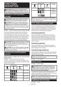
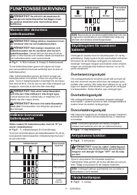
CAUTION:
Do not look in the light or see the
source of light directly.
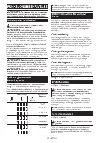
Pull the switch trigger to light up the lamp. The lamp
keeps on lighting while the switch trigger is being pulled.
The lamp goes out approximately 10 seconds after
releasing the switch trigger.
NOTE:
When the tool is overheated, the tool stops
automatically and the lamp starts flashing. In this
case, release the switch trigger. The lamp turns off in
one minute.
NOTE:
Use a dry cloth to wipe the dirt off the lens of
the lamp. Be careful not to scratch the lens of lamp, or
it may lower the illumination.
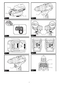
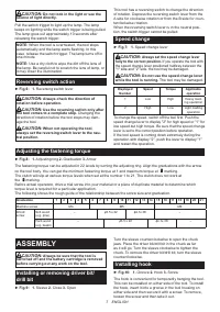
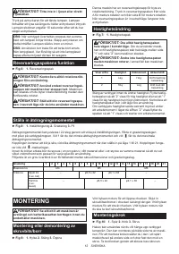
Reversing switch action
►
Fig.6:
1.
Reversing switch lever
CAUTION:
Always check the direction of
rotation before operation.
CAUTION:
Use the reversing switch only after
the tool comes to a complete stop.
Changing the
direction of rotation before the tool stops may dam
-
age the tool.
CAUTION:
When not operating the tool,
always set the reversing switch lever to the neu-
tral position.
This tool has a reversing switch to change the direction
of rotation. Depress the reversing switch lever from the
A side for clockwise rotation or from the B side for coun
-
terclockwise rotation.
When the reversing switch lever is in the neutral posi
-
tion, the switch trigger cannot be pulled.
Speed change
►
Fig.7:
1.
Speed change lever
CAUTION:
Always set the speed change lever
fully to the correct position.
If you operate the tool with
the speed change lever positioned halfway between the
"1" side and "2" side, the tool may be damaged.
CAUTION:
Do not use the speed change lever
while the tool is running.
The tool may be damaged.
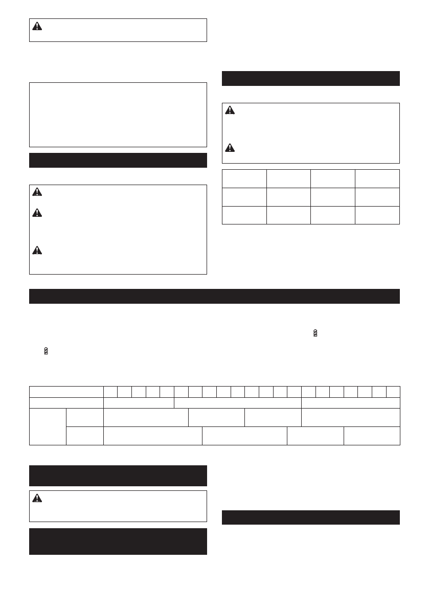
Displayed
Number
Speed
Torque
Applicable
operation
1
Low
High
Heavy load-
ing operation
2
High
Low
Light loading
operation
To change the speed, switch off the tool first. Push the
speed change lever to display "2" for high speed or "1" for
low speed but high torque. Be sure that the speed change
lever is set to the correct position before operation.
If the tool speed is coming down extremely during the
operation with display "2", push the lever to display "1"
and restart the operation.
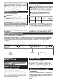
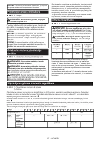
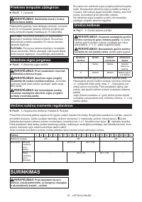
Adjusting the fastening torque
►
Fig.8:
1.
Adjusting ring
2.
Graduation
3.
Arrow
The fastening torque can be adjusted in 22 levels by turning the adjusting ring. Align the graduations with the arrow
on the tool body. You can get the minimum fastening torque at 1 and maximum torque at
marking.
The clutch will slip at various torque levels when set at the number 1 to 21. The clutch does not work at
the
marking.
Before actual operation, drive a trial screw into your material or a piece of duplicate material to determine which
torque level is required for a particular application.
The following shows the rough guide of the relationship between the screw size and graduation.
Graduation
1
2
3
4
5
6
7
8
9
10 11 12 13 14
15
16
17
18 19 20 21
Machine screw
M4
M5
M6
Wood
screw
Soft wood
(e.g. pine)
–
ɸ
3.5 x 22
ɸ
4.1x 38
–
Hard wood
(e.g. lauan)
–
ɸ
3.5 x 22
ɸ
4.1x 38
–
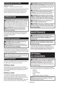
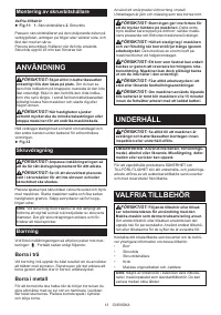
ASSEMBLY
CAUTION:
Always be sure that the tool is
switched off and the battery cartridge is removed
before carrying out any work on the tool.
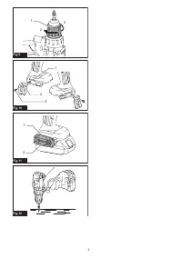
Installing or removing driver bit/
drill bit
►
Fig.9:
1.
Sleeve
2.
Close
3.
Open
Turn the sleeve counterclockwise to open the chuck
jaws. Place the driver bit/drill bit in the chuck as far
as it will go. Turn the sleeve clockwise to tighten the
chuck. To remove the driver bit/drill bit, turn the sleeve
counterclockwise.
Installing hook
►
Fig.10:
1.
Groove
2.
Hook
3.
Screw
The hook is convenient for temporarily hanging the tool.
This can be installed on either side of the tool. To install
the hook, insert it into a groove in the tool housing on
either side and then secure it with a screw. To remove,
loosen the screw and then take it out.
Характеристики

Остались вопросы?Не нашли свой ответ в руководстве или возникли другие проблемы? Задайте свой вопрос в форме ниже с подробным описанием вашей ситуации, чтобы другие люди и специалисты смогли дать на него ответ. Если вы знаете как решить проблему другого человека, пожалуйста, подскажите ему :)


