Шуруповерты Makita DDF343SHE - инструкция пользователя по применению, эксплуатации и установке на русском языке. Мы надеемся, она поможет вам решить возникшие у вас вопросы при эксплуатации техники.
Если остались вопросы, задайте их в комментариях после инструкции.
"Загружаем инструкцию", означает, что нужно подождать пока файл загрузится и можно будет его читать онлайн. Некоторые инструкции очень большие и время их появления зависит от вашей скорости интернета.


6
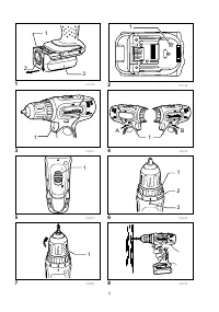
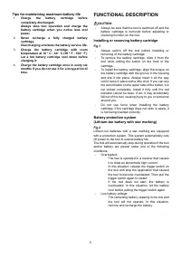
Switch action
Fig.3
CAUTION:
•
Before inserting the battery cartridge into the tool,
always check to see that the switch trigger actuates
properly and returns to the "OFF" position when
released.
To start the tool, simply pull the switch trigger. Tool speed
is increased by increasing pressure on the switch trigger.
Release the switch trigger to stop.
Reversing switch action
Fig.4
This tool has a reversing switch to change the direction of
rotation. Depress the reversing switch lever from the A
side for clockwise rotation or from the B side for
counterclockwise rotation.
When the reversing switch lever is in the neutral position,
the switch trigger cannot be pulled.
CAUTION:
•
Always check the direction of rotation before
operation.
•
Use the reversing switch only after the tool comes
to a complete stop. Changing the direction of
rotation before the tool stops may damage the tool.
•
When not operating the tool, always set the
reversing switch lever to the neutral position.
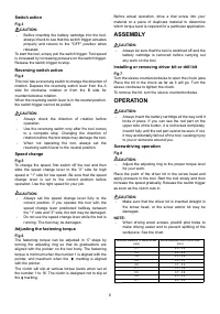
Speed change
Fig.5
To change the speed, first switch off the tool and then
slide the speed change lever to the "2" side for high
speed or "1" side for low speed. Be sure that the speed
change lever is set to the correct position before
operation. Use the right speed for your job.
CAUTION:
•
Always set the speed change lever fully to the
correct position. If you operate the tool with the
speed change lever positioned halfway between
the "1" side and "2" side, the tool may be damaged.
•
Do not use the speed change lever while the tool is
running. The tool may be damaged.
Adjusting the fastening torque
Fig.6
The fastening torque can be adjusted in 17 steps by
turning the adjusting ring so that its graduations are
aligned with the pointer on the tool body. The fastening
torque is minimum when the number 1 is aligned with the
pointer, and maximum when the
marking is aligned
with the pointer.
The clutch will slip at various torque levels when set at
the number 1 to 16. The clutch is designed not to slip at
the
marking.
Before actual operation, drive a trial screw into your
material or a piece of duplicate material to determine
which torque level is required for a particular application.
ASSEMBLY
CAUTION:
•
Always be sure that the tool is switched off and the
battery cartridge is removed before carrying out
any work on the tool.
Installing or removing driver bit or drill bit
Fig.7
Turn the sleeve counterclockwise to open the chuck jaws.
Place the bit in the chuck as far as it will go. Turn the
sleeve clockwise to tighten the chuck.
To remove the bit, turn the sleeve counterclockwise.
OPERATION
CAUTION:
•
Always insert the battery cartridge all the way until it
locks in place. If you can see the red part on the
upper side of the button, it is not locked completely.
Insert it fully until the red part cannot be seen. If not,
it may accidentally fall out of the tool, causing injury
to you or someone around you.
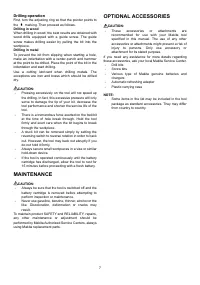
Screwdriving operation
Fig.8
CAUTION:
•
Adjust the adjusting ring to the proper torque level
for your work.
Place the point of the driver bit in the screw head and
apply pressure to the tool. Start the tool slowly and then
increase the speed gradually. Release the switch trigger
as soon as the clutch cuts in.
CAUTION:
•
Make sure that the driver bit is inserted straight in
the screw head, or the screw and/or bit may be
damaged.
NOTE:
•
When driving wood screws, predrill pilot holes to
make driving easier and to prevent splitting of the
workpiece. See the chart.
Nominal diameter of wood screw
(mm)
Recommended size of pilot hole
(mm)
3.1
2.0 - 2.2
3.5
2.2 - 2.5
3.8
2.5 - 2.8
4.5
2.9 - 3.2
4.8
3.1 - 3.4
5.1
3.3 - 3.6
5.5
3.7 - 3.9
5.8
4.0 - 4.2
6.1
4.2 - 4.4
006421
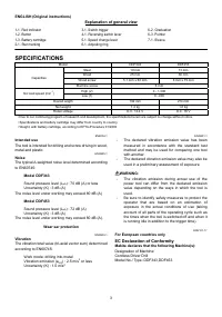
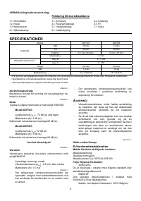
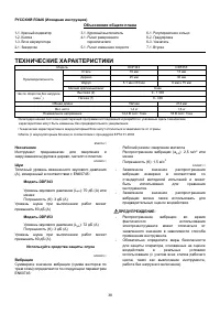
Характеристики

Остались вопросы?Не нашли свой ответ в руководстве или возникли другие проблемы? Задайте свой вопрос в форме ниже с подробным описанием вашей ситуации, чтобы другие люди и специалисты смогли дать на него ответ. Если вы знаете как решить проблему другого человека, пожалуйста, подскажите ему :)


