Шуруповерты Makita DDF 481 RT3J - инструкция пользователя по применению, эксплуатации и установке на русском языке. Мы надеемся, она поможет вам решить возникшие у вас вопросы при эксплуатации техники.
Если остались вопросы, задайте их в комментариях после инструкции.
"Загружаем инструкцию", означает, что нужно подождать пока файл загрузится и можно будет его читать онлайн. Некоторые инструкции очень большие и время их появления зависит от вашей скорости интернета.


6
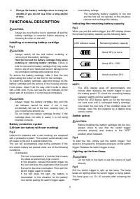
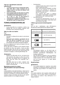
NOTE:
•
When the tool is overheated, the tool stops
automatically and the lamp starts flashing. In this
case, release the switch trigger. The lamp turns off
in one minute.
•
Use a dry cloth to wipe the dirt off the lens of lamp.
Be careful not to scratch the lens of lamp, or it
may lower the illumination.
Reversing switch action
CAUTION:
•
Always check the direction of rotation before
operation.
•
Use the reversing switch only after the tool comes
to a complete stop. Changing the direction of
rotation before the tool stops may damage the tool.
•
When not operating the tool, always set the
reversing switch lever to the neutral position.
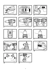
Fig.6
This tool has a reversing switch to change the direction
of rotation. Depress the reversing switch lever from the
A side for clockwise rotation or from the B side for
counterclockwise rotation.
When the reversing switch lever is in the neutral
position, the switch trigger cannot be pulled.
Speed change
CAUTION:
•
Always set the speed change lever fully to the
correct position. If you operate the tool with the
speed change lever positioned halfway between
the "1" side and, "2" side, the tool may be
damaged.
•
Do not use the speed change lever while the tool
is running. The tool may be damaged.
Fig.7
To change the speed, first switch off the tool and then
slide the speed change lever to the "2" side for high
speed or, "1" side for low speed. Be sure that the speed
change lever is set to the correct position before
operation. Use the right speed for your job.
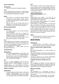
Selecting the action mode
CAUTION:
•
Always set the ring correctly to your desired mode
mark. If you operate the tool with the ring
positioned halfway between the mode marks, the
tool may be damaged.
Fig.8
This tool has an action mode changing ring. For drilling,
turn the ring so that the arrow on the tool body points
toward the
mark on the ring. For screwing, turn the
ring so that the arrow points toward the
mark on the
ring.
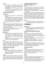
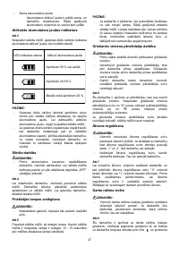
Adjusting the fastening torque
(screwdriver mode "
")
Fig.9
The fastening torque can be adjusted in 21 steps by
turning the adjusting ring so that its graduations are
aligned with the pointer on the tool body.
First, slide the action mode change lever to the position
of
symbol.
The fastening torque is minimum when the number 1 is
aligned with the pointer, and maximum when the
marking is aligned with the pointer. The clutch will slip at
various torque levels when set at the number 1 to 21.
Before actual operation, drive a trial screw into your
material or a piece of duplicate material to determine
which torque level is required for a particular application.
NOTE:
•
The adjusting ring does not lock when the pointer is
positioned only halfway between the graduations.
ASSEMBLY
CAUTION:
•
Always be sure that the tool is switched off and the
battery cartridge is removed before carrying out
any work on the tool.
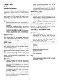
Installing side grip (auxiliary handle)
Fig.10
Always use the side grip to ensure operating safety.
Insert the side grip so that the groove on the arm fit in
one of the counter parts on the tool. Then tighten the
grip by turning clockwise.
Depending the operations, you can install the side grip
either right or left side of the tool.
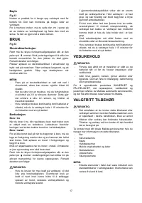
Installing or removing driver bit or drill bit
Fig.11
Turn the sleeve counterclockwise to open the chuck
jaws. Place the bit in the chuck as far as it will go. Turn
the sleeve clockwise to tighten the chuck. To remove
the bit, turn the sleeve counterclockwise.
Installing bit holder
Fig.12
Fit the bit holder into the protrusion at the tool foot on
either right or left side and secure it with a screw.
When not using the driver bit, keep it in the bit holders.
Bits 45 mm long can be kept there.
Hook
Fig.13
The hook is convenient for temporarily hanging the tool.
This can be installed on either side of the tool.
To install the hook, insert it into a groove in the tool
housing on either side and then secure it with a screw.
To remove, loosen the screw and then take it out.
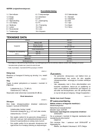
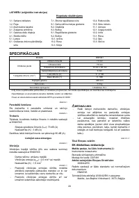
Характеристики

Остались вопросы?Не нашли свой ответ в руководстве или возникли другие проблемы? Задайте свой вопрос в форме ниже с подробным описанием вашей ситуации, чтобы другие люди и специалисты смогли дать на него ответ. Если вы знаете как решить проблему другого человека, пожалуйста, подскажите ему :)


