
Шуруповерты GRAPHITE 58G722 - инструкция пользователя по применению, эксплуатации и установке на русском языке. Мы надеемся, она поможет вам решить возникшие у вас вопросы при эксплуатации техники.
Если остались вопросы, задайте их в комментариях после инструкции.
"Загружаем инструкцию", означает, что нужно подождать пока файл загрузится и можно будет его читать онлайн. Некоторые инструкции очень большие и время их появления зависит от вашей скорости интернета.


11
•
Set desired drilling depth.
•
Fix by tightening the wheel lock of the additional handle (
7
) collar.
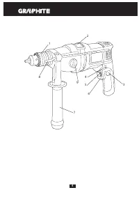
INSTALLATION OF WORKING TOOLS
Disconnect the power tool from power supply.
•
Insert key into one of the holes on the circumference of the drill
chuck (
1
).
•
Open jaws to desired dimension.
•
Insert cylindrical drill shank into the drill chuck (
1
), push it to the limit.
•
Tighten jaws on drill shank with the key (insert it into three holes
on the drill chuck circumference).
Remember to always remove the key from the chuck, after you
finish drill installation or removal.
OPERATION / SETTINGS
SWITCHING ON / SWITCHING OFF
The mains voltage must match the voltage on the label of the drill.
Switching on
– press the switch button (
6
) and hold in this position.
Switching off
– release pressure on the switch (
6
).
Locking the switch (continuous operation)
Switching on:
•
Press the switch button (
6
) and hold in this position.
•
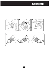
Press the switch lock button (
3
) (
fig. A
).
•
Release pressure on the switch button (
6
).
Switching off:
•
Press and release the switch button (
6
).
Range of rotational speed of the spindle is controlled with
pressure on the switch button.
WHEEL FOR SPINDLE SPEED ADJUSTMENT
The drill allows for operation with different spindle speeds. It can
be controlled with the wheel (
5
) (
fig. A
). For each setting of the
wheel for speed control, the speed can be adjusted continuously by
increasing or decreasing pressure on the switch button (
6
).
•
Increase the speed by turning the wheel (
5
) clockwise.
•
Reduce the speed by turning the wheel (
5
) counter clockwise.
* Refer to graphic symbols on the wheel for rotational speed control or the switch.
Choose proper rotational speed when the drill operates with no
load, with pressed switch lock button. Defined speed may decrease
under load.
CHANGE OF GEAR
Drill is equipped with gear switch (
9
), which broadens the range of
rotational speed (
fig. E
).
Gear I
: lower range of rotational speed – for large diameter holes or
for processing hard material.
Gear II
: higher range of rotational speed – for small diameter holes
or for processing soft material.
Set the gear switch (
9
) in appropriate position depending on the
processed material. When the switch is blocked and cannot be
moved, turn the spindle slightly.
Never change position of the gear switch while the drill is
operating. It may damage the power tool.
LEFT – RIGHT DIRECTION OF ROTATION
Choose direction of spindle rotation with the selector switch (
4
) (
fig. A
).
Clockwise rotation
– set the switch (
4
) to the extreme left position.
Counter clockwise rotation
– set the switch (
4
) to the extreme right
position.
* In certain cases position of the direction selector switch relating to rotation direction may be different
than specified. Please refer to graphic signs placed on the switch or tool body.
Do not change direction of rotation when the spindle of the drill
is rotating. Ensure the position of the direction selector switch is
correct before starting the tool.
OPERATION MODE SWITCH
Operation mode switch (
2
) allows for choosing suitable work mode:
drilling with or without impact (
fig. B
). Set the operation mode
switch in the position for drilling without impact (drill symbol),
when processing materials like metal, wood, ceramics, plastics and
alike. Set the operation mode switch in the position for drilling with
impact (hammer symbol), when processing materials like stone,
concrete, brick and alike. Holes in wood, wood based materials and
metals can be made with drills of high speed steel or carbon steel
(the latter for wood and wood based materials only). For impact
drilling special drills with sintered carbide inserts should be used.
You should not use counter clockwise rotation when impact
function is on.
Long lasting drilling at low rotational speed of the spindle
may cause motor overheating. Provide regular breaks during
operation or let the tool operate at maximum speed with no load
for approximately 1–2 minutes. Do not cover holes for motor
ventilation in the tool body.
OPERATION AND MAINTENANCE
Unplug the power cord from mains socket before commencing
any activities related to installation, adjustment, repair or
maintenance.
MAINTENANCE AND STORAGE
•
Cleaning the device after each use is recommended.
•
Do not use water or any other liquid for cleaning.
•
Clean the tool with a dry cloth or blow through with compressed
air at low pressure.
•
Do not use any cleaning agents or solvents, they may damage
plastic parts.
•
Clean ventilation holes in the motor casing regularly to prevent
device overheating.
•
In case of power cord damage replace it with a cord with the same
specification. Entrust the repair to a qualified specialist or return
the tool to a service point.
•
In case of excessive commutator sparking, have the technical
condition of carbon brushes of the motor checked by a qualified
person.
•
Always store the tool in a dry place, beyond reach of children.
DRILL CHUCK REPLACEMENT
•
Open drill chuck (
1
) jaws.
•
Unscrew the drill chuck fixing screw with cross screwdriver, by
turning it clockwise (left-hand thread).
•
Install hex key in the drill chuck (
fig. D
).
•
Gently tap on the free end of the hexagonal key.
•
Unscrew the drill chuck.
Installation of the drill chuck is similar to deinstallation, only the
sequence of actions is reversed.
REPLACEMENT OF CARBON BRUSHES
Immediately replace worn out (shorter than 5 mm), burnt or
cracked motor carbon brushes. Always replace both carbon
brushes at a time. Entrust replacement of carbon brushes only to
a qualified person. Only original parts should be used.
All defects should be repaired by service workshop authorized by
the manufacturer.
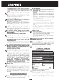
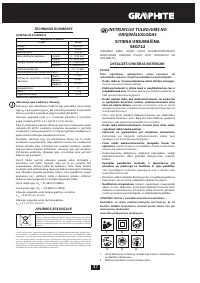
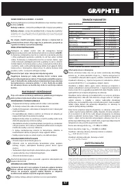
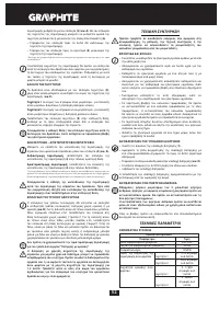
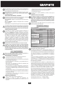
TECHNICAL PARAMETERS
RATED PARAMETERS
Impact Drill
Parameter
Value
Supply voltage
230 V AC
Power supply frequency
50 Hz
Rated power
1050 W
Supply voltage
Gear 1
0 - 1100 min
-1
Gear 2
0 - 3000 min
-1


