
Шлифмашины Makita M9508 - инструкция пользователя по применению, эксплуатации и установке на русском языке. Мы надеемся, она поможет вам решить возникшие у вас вопросы при эксплуатации техники.
Если остались вопросы, задайте их в комментариях после инструкции.
"Загружаем инструкцию", означает, что нужно подождать пока файл загрузится и можно будет его читать онлайн. Некоторые инструкции очень большие и время их появления зависит от вашей скорости интернета.
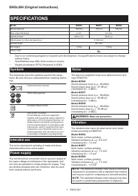


7 ENGLISH
FUNCTIONAL
DESCRIPTION
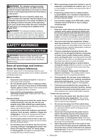
CAUTION:
Always be sure that the tool is
switched off and unplugged before adjusting or
checking function on the tool.
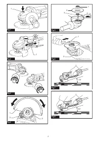
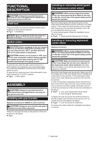
Shaft lock
Press the shaft lock to prevent spindle rotation when
installing or removing accessories.
►
Fig.1:
1.
Shaft lock
NOTICE:
Never actuate the shaft lock when the
spindle is moving.
The tool may be damaged.
Switch action
CAUTION:
Before plugging in the tool, always
check to see that the slide switch actuates prop-
erly and returns to the "OFF" position when the
rear of the slide switch is depressed.
CAUTION:
Switch can be locked in "ON" posi-
tion for ease of operator comfort during extended
use. Apply caution when locking tool in "ON"
position and maintain firm grasp on tool.
To start the tool, slide the slide switch toward the “I
(ON)” position by pushing the rear of the slide switch.
For continuous operation, press the front of the slide
switch to lock it.
To stop the tool, press the rear of the slide switch, then
slide it toward the “O (OFF)” position.
►
Fig.2:
1.
Slide switch
ASSEMBLY
CAUTION:
Always be sure that the tool is
switched off and unplugged before carrying out
any work on the tool.
Installing side grip (handle)
Optional accessory for M9506 in some countries
CAUTION:
Always be sure that the side grip is
installed securely before operation.
Screw the side grip securely on the position of the tool
as shown in the figure.
►
Fig.3
Installing or removing wheel guard
(For depressed center wheel)
WARNING:
When using a depressed center
wheel, the wheel guard must be fitted on the tool
so that the closed side of the guard always points
toward the operator.
Mount the wheel guard with the protrusions on the
wheel guard band aligned with the notches on the bear
-
ing box. Then rotate the wheel guard to such an angle
that it can protect the operator according to work. Be
sure to tighten the screw securely.
To remove wheel guard, follow the installation proce-
dure in reverse.
►
Fig.4:
1.
Wheel guard
2.
Bearing box
3.
Screw
Installing or removing depressed
center wheel
Optional accessory
WARNING:
When using a depressed center
wheel, the wheel guard must be fitted on the tool
so that the closed side of the guard always points
toward the operator.
CAUTION:
Make sure that the mounting part
of the inner flange fits into the inner diameter of
the depressed center wheel perfectly.
Mounting
the inner flange on the wrong side may result in the
dangerous vibration.
Mount the inner flange onto the spindle. Make sure to fit
the straight part of the inner flange onto the straight part
at the bottom of the spindle. Fit the depressed center
wheel on the inner flange and screw the lock nut onto
the spindle.
In case of mounting a depressed center wheel thinner
than 4 mm (5/32"), place the lock nut so that the protru-
sion on the lock nut faces outside. Otherwise, place it
so that the protrusion on it fits into the inner diameter of
the wheel.
►
Fig.5:
1.
Lock nut
2.
Depressed center wheel
3.
Inner flange
4.
Mounting part
To tighten the lock nut, press the shaft lock firmly so
that the spindle cannot revolve, then use the lock nut
wrench and securely tighten clockwise.
►
Fig.6:
1.
Lock nut wrench
2.
Shaft lock
To remove the wheel, follow the installation procedure
in reverse.
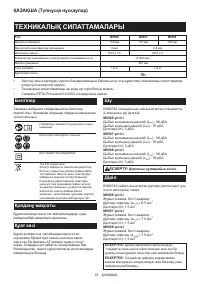
Характеристики

Остались вопросы?Не нашли свой ответ в руководстве или возникли другие проблемы? Задайте свой вопрос в форме ниже с подробным описанием вашей ситуации, чтобы другие люди и специалисты смогли дать на него ответ. Если вы знаете как решить проблему другого человека, пожалуйста, подскажите ему :)


