
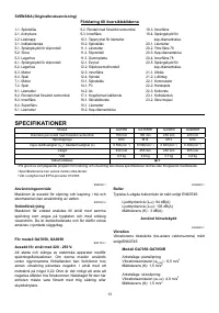
Шлифмашины Makita GA7050 - инструкция пользователя по применению, эксплуатации и установке на русском языке. Мы надеемся, она поможет вам решить возникшие у вас вопросы при эксплуатации техники.
Если остались вопросы, задайте их в комментариях после инструкции.
"Загружаем инструкцию", означает, что нужно подождать пока файл загрузится и можно будет его читать онлайн. Некоторые инструкции очень большие и время их появления зависит от вашей скорости интернета.


9
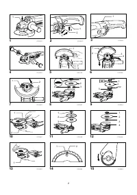
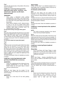
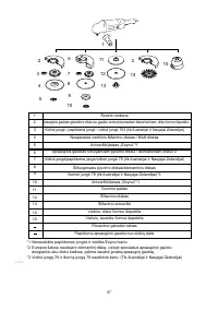
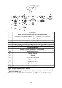
Fig.4
Screw the side grip securely on the position of the tool as
shown in the figure.
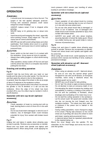
Installing or removing wheel guard (For
depressed center wheel , multi disc , wire
wheel brush / abrasive cut-off wheel ,
diamond wheel)
WARNING:
•
When using a depressed center grinding
wheel/Multi-disc, flex wheel or wire wheel brush,
the wheel guard must be fitted on the tool so that
the closed side of the guard always points toward
the operator.
•
When using an abrasive cut-off / diamond wheel,
be sure to use only the special wheel guard
designed for use with cut-off wheels. (In European
countries, when using a diamond wheel, the
ordinary guard can be used.)
For tool with locking screw type wheel guard
Fig.5
Mount the wheel guard with the protrusion on the wheel
guard band aligned with the notch on the bearing box.
Then rotate the wheel guard around 180 degrees
counterclockwise. Be sure to tighten the screw securely.
To remove wheel guard, follow the installation procedure
in reverse.
For tool with clamp lever type wheel guard
Fig.6
Fig.7
Loosen the lever on the wheel guard. Mount the wheel
guard with the protrusion on the wheel guard band
aligned with the notch on the bearing box. Then rotate
the wheel guard around to the position shown in the
figure. Tighten the lever to fasten the wheel guard. If the
lever is too tight or too loose to fasten the wheel guard,
loosen or tighten the nut to adjust the tightening of the
wheel guard band.
To remove wheel guard, follow the installation procedure
in reverse.
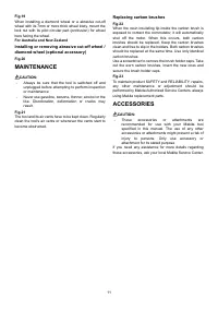
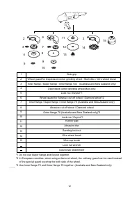
Installing or removing depressed center
grinding wheel/Multi-disc (accessory)
WARNING:
•
Always use supplied guard when depressed center
grinding wheel/Multi-disc is on tool. Wheel can
shatter during use and guard helps to reduce
chances of personal injury.
Fig.8
Mount the inner flange onto the spindle. Fit the
wheel/disc on the inner flange and screw the lock nut
onto the spindle.
WARNING:
•
Never use a more than 6.5 mm thick grinding
wheel.
Super flange
Models with the letter F are standard-equipped with a
super flange. Only 1/3 of efforts needed to undo lock nut,
compared with conventional type.
For Australia and New Zealand
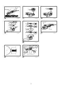
Fig.9
Mount the inner flange onto the spindle. Fit the
wheel/disc on the inner flange and screw the lock nut
with its protrusion facing downward (facing toward the
wheel).
To tighten the lock nut, press the shaft lock firmly so that
the spindle cannot revolve, then use the lock nut wrench
and securely tighten clockwise.
Fig.10
To remove the wheel, follow the installation procedure in
reverse.
Installing or removing abrasive disc (optional
accessory)
NOTE:
•
Use sander accessories specified in this manual.
These must be purchased separately.
Fig.11
Mount the rubber pad onto the spindle. Fit the disc on the
rubber pad and screw the lock nut onto the spindle. To
tighten the lock nut, press the shaft lock firmly so that the
spindle cannot revolve, then use the lock nut wrench and
securely tighten clockwise.
To remove the disc, follow the installation procedure in
reverse.
Installing or removing Ezynut (optional
accessory)
CAUTION:
•
Do not use Ezynut with Super Flange or angle
grinder with "F" on the end of the model No. Those
flanges are so thick that the entire thread cannot be
retained by the spindle.
Fig.12
Mount inner flange , abrasive wheel/Multi-disc and
Ezynut onto the spindle so that Makita Logo on Ezynut
faces outside.
Fig.13
Press shaft lock firmly and tighten Ezynut by turning the
abrasive wheel/Multi-disc clockwise as far as it turns.
Turn the outside ring of Ezynut counterclockwise to
loosen.
Fig.14
Fig.15
NOTE:
•
Ezynut can be loosened by hand as long as the
arrow points the notch. Otherwise a lock nut
wrench is required to loosen it. Insert one pin of the
wrench into a hole and turn Ezynut
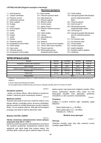
Характеристики

Остались вопросы?Не нашли свой ответ в руководстве или возникли другие проблемы? Задайте свой вопрос в форме ниже с подробным описанием вашей ситуации, чтобы другие люди и специалисты смогли дать на него ответ. Если вы знаете как решить проблему другого человека, пожалуйста, подскажите ему :)


