Шлифмашины Bosch GWS 180-LI (0.601.9H9.020) - инструкция пользователя по применению, эксплуатации и установке на русском языке. Мы надеемся, она поможет вам решить возникшие у вас вопросы при эксплуатации техники.
Если остались вопросы, задайте их в комментариях после инструкции.
"Загружаем инструкцию", означает, что нужно подождать пока файл загрузится и можно будет его читать онлайн. Некоторые инструкции очень большие и время их появления зависит от вашей скорости интернета.


22
| English
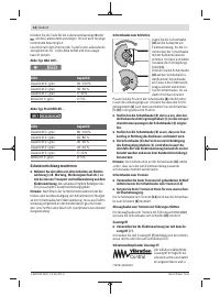
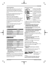
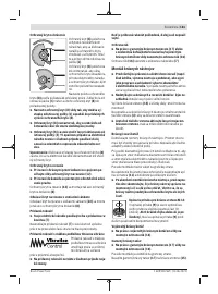
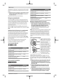
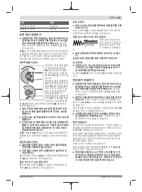
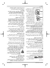
requirements of the operation. To do this, push the unlock-
ing lever
(1)
upward and rotate the protective guard
(8)
into
the required position.
u
Always position the protective guard
(8)
such that the
two cams on the unlocking lever
(1)
engage in the
corresponding openings on the protective guard
(8).
u
Adjust the protective guard
(8)
such that sparking in
the direction of the operator is prevented.
u
The protective guard
(8)
must only be adjustable
while the unlocking lever (1)
is actuated. Otherwise,
the power tool must not be used any more under any
circumstances and must be sent to the after-sales ser-
vice.
Note:
The coding cams on the protective guard
(8)
ensure
that only a protective guard that is suitable for the power
tool can be fitted.
Protective guard for cutting
u
Always use the protective guard for cutting (12) when
cutting with bonded abrasives.
u
Provide sufficient dust extraction when cutting stone.
The protective guard for cutting
(12)
is fitted in the same
way as the protective guard for grinding
(8)
.
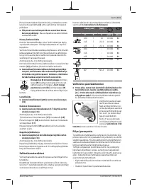
Extraction guard for cutting with a guide block
The extraction guard for cutting with a guide block
(22)
is fit-
ted in the same way as the protective guard for grinding
(8)
.
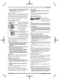
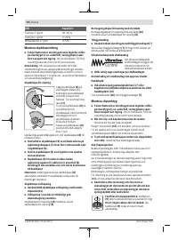
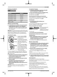
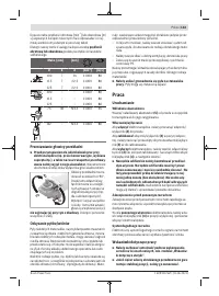
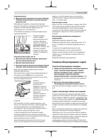
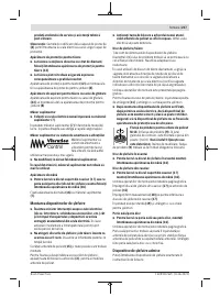
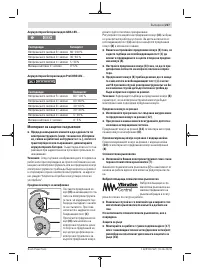
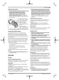
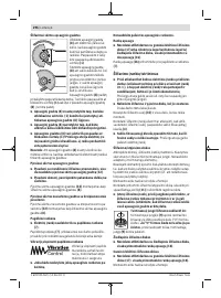
Side handle
u
Do not operate your power tool without the side
handle
(7)
.
Screw the side handle
(7)
on the left or right of the machine
head depending on how your are working.
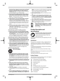
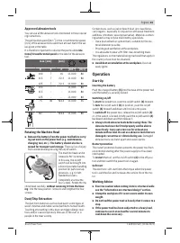
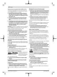
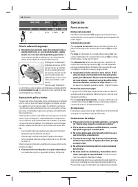
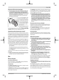
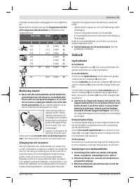
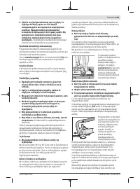
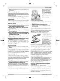
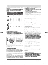
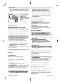
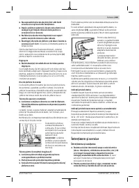
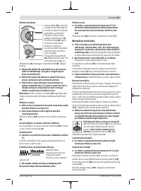
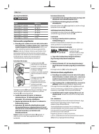
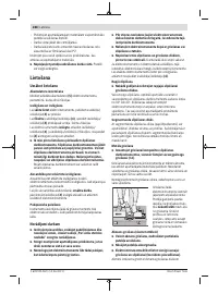
Low-vibration auxiliary handle
The low-vibration auxiliary
handle reduces vibration,
enabling the tool to be used
safely and more comfort-
ably.
u
Do not make any alterations of any kind to the auxili-
ary handle.
Do not continue to use a damaged auxiliary handle.
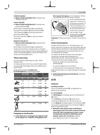
Hand guard
u
Always fit the hand guard (16)
when working with the
rubber sanding plate
(17)
or with the cup brush/disc
brush/flap disc.
Attach the hand guard
(16)
to the side handle
(7)
.
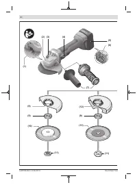
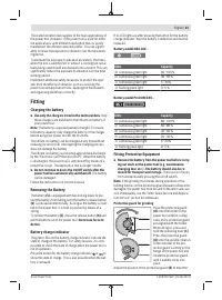
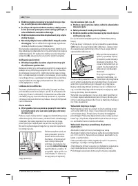
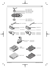
Fitting the Abrasive Tools
u
Remove the battery from the power tool before carry-
ing out work on the power tool (e.g. maintenance,
changing tool, etc.). The battery should also be re-
moved for transport and storage.
There is risk of injury
from unintentionally pressing the on/off switch.
u
Do not touch grinding and cutting discs until they have
cooled down.
The discs can become very hot while work-
ing.
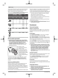
Clean the grinding spindle
(15)
and all the parts to be fitted.
Lock the grinding spindle with the spindle lock button
(3)
before clamping and releasing the abrasive tools.
u
Do not press the spindle lock button while the grind-
ing spindle is moving.
The power tool may become dam-
aged if you do this.
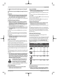
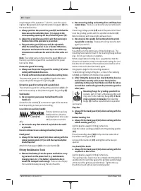
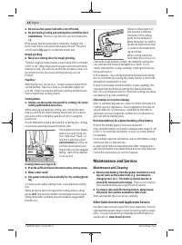
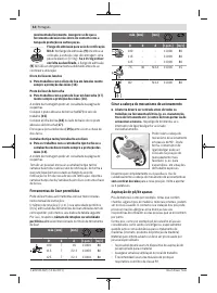
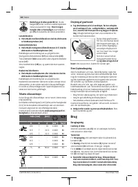
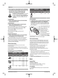
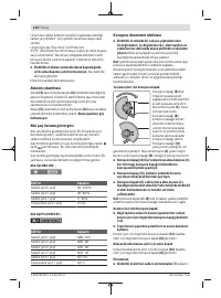
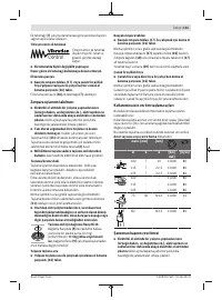
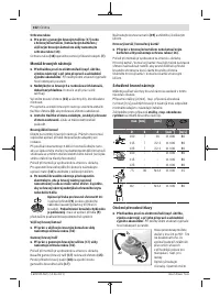
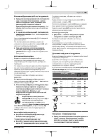
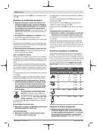
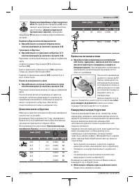
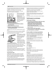
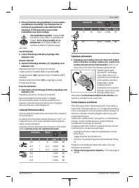
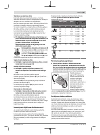
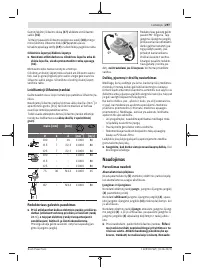
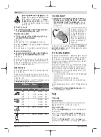
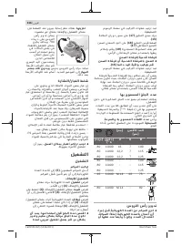
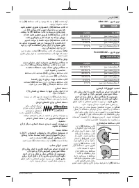
Grinding/Cutting Disc
Pay attention to the dimensions of the grinding tools. The
mounting hole diameter must fit the mounting flange without
play. Do not use reducers or adapters.
When using diamond cutting discs, pay attention that the
direction-of-rotation arrow on the diamond cutting disc and
the direction of rotation of the machine (see direction-of-ro-
tation arrow on the machine head) agree.
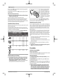
See graphics page for the mounting sequence.
To fasten the grinding/cutting disc, screw on the clamping
nut
(11)
and tighten with the two-hole spanner.
u
After fitting the abrasive tool, check that the abrasive
tool is fitted correctly and can turn freely before
switching on the power tool. Make sure that the abras-
ive tool does not brush against the protective guard or
other parts.
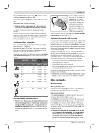
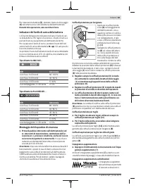
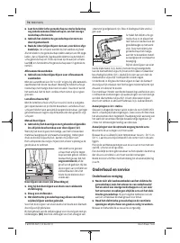
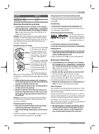
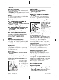
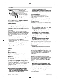
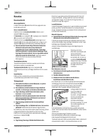
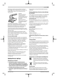
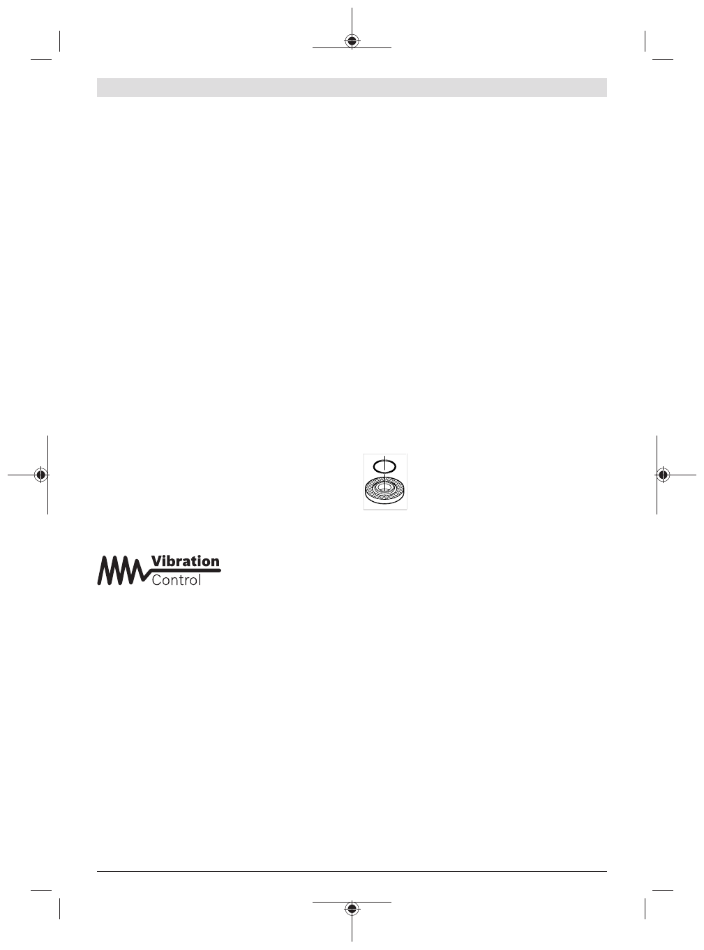
Mounting flange for grinding spindle M 14:
A plastic part (O-ring) is fitted around the cent-
ring collar in the mounting flange
(9)
.
If the O-
ring is missing or damaged,
the mounting
flange
(9)
must be replaced before operation
can resume.
Flap disc
u
Always fit the hand guard (16)
when working with the
flap disc.
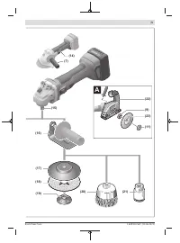
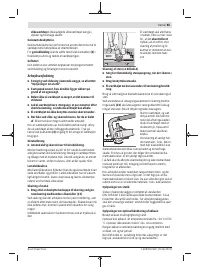
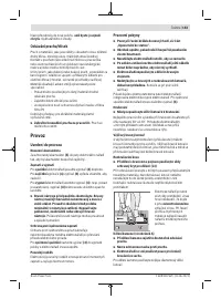
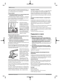
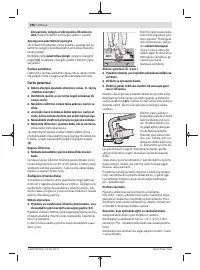
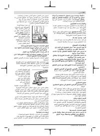
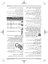
Rubber Sanding Pad
u
Always fit the hand guard
(16)
when working with the
rubber sanding pad (17)
.
See the graphics page for fitting instructions.
Slide the rubber sanding pad
(17)
onto the grinding spindle
(15)
.
Press the sanding sheet
(18)
firmly onto the underside of
the rubber sanding pad
(17)
.
Screw on the round nut
(19)
and tighten with a two-pin
spanner.
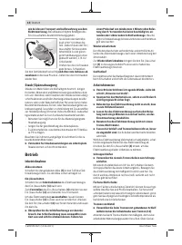
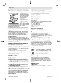
Cup brush/disc brush
u
Always fit the hand guard
(16)
when working with the
cup brush or disc brush.
See the graphics page for fitting instructions.
The cup brush/disc brush must be screwed onto the grinding
spindle until it rests firmly against the grinding spindle flange
at the end of the grinding spindle thread. Tighten the cup
brush/disc brush with an open-ended spanner.
1 609 92A 5GT | (14.06.2021)
Bosch Power Tools
Содержание
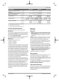
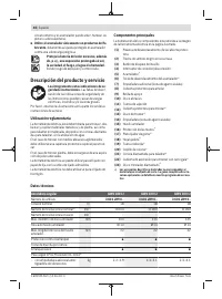
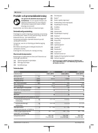
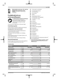
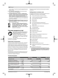
- 180 Описание продукта и услуг; Применение по назначению
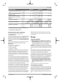
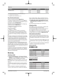
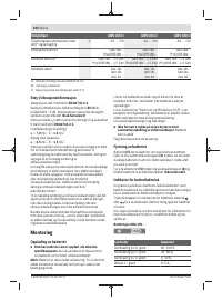
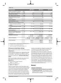
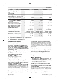
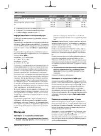
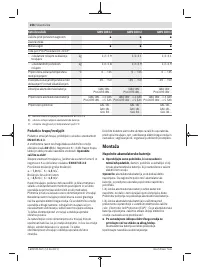
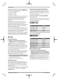
- 181 Данные по шуму и вибрации; Сборка; Зарядка аккумулятора
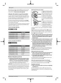
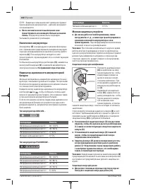
- 184 Работа с инструментом; Включение электроинструмента
- 186 Техобслуживание и сервис; Техобслуживание и очистка
- 187 Українська; Вказівки з техніки безпеки; Загальні застереження для електроприладів; ДЖЕННЯ
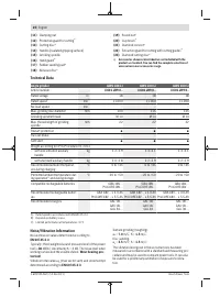
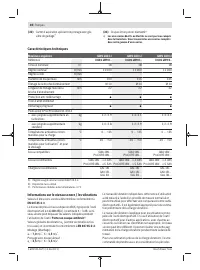
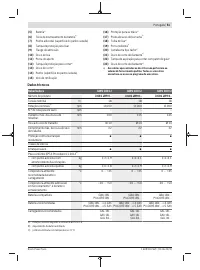
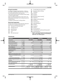
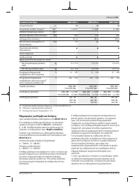
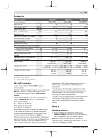
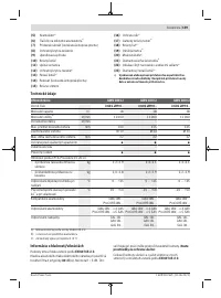
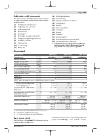
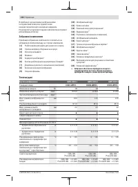
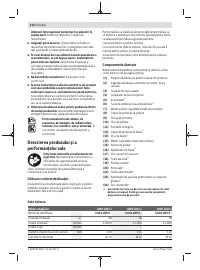
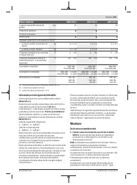
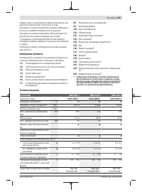
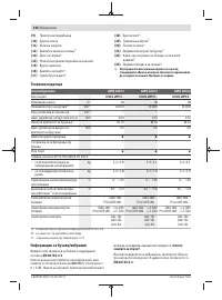
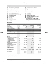
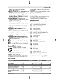
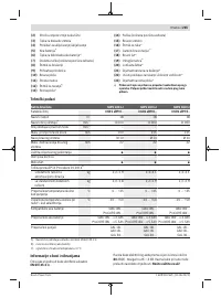
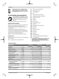
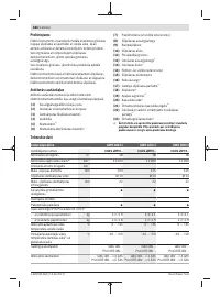
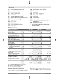
Характеристики

Остались вопросы?Не нашли свой ответ в руководстве или возникли другие проблемы? Задайте свой вопрос в форме ниже с подробным описанием вашей ситуации, чтобы другие люди и специалисты смогли дать на него ответ. Если вы знаете как решить проблему другого человека, пожалуйста, подскажите ему :)


