Памяти и накопители SEAGATE (ST8000VX004) - инструкция пользователя по применению, эксплуатации и установке на русском языке. Мы надеемся, она поможет вам решить возникшие у вас вопросы при эксплуатации техники.
Если остались вопросы, задайте их в комментариях после инструкции.
"Загружаем инструкцию", означает, что нужно подождать пока файл загрузится и можно будет его читать онлайн. Некоторые инструкции очень большие и время их появления зависит от вашей скорости интернета.


Seagate SkyHawk Serial ATA Product Manual, Rev. B
23
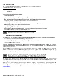
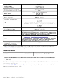
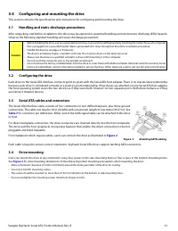
4.0
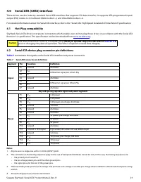
Serial ATA (SATA) interface
These drives use the industry-standard Serial ATA interface that supports FIS data transfers. It supports ATA programmed input/
output (PIO) modes 0–4; multiword DMA modes 0–2, and Ultra DMA modes 0–6.
For detailed information about the Serial ATA interface, refer to the “Serial ATA: High Speed Serialized AT Attachment” specification.
4.1
Hot-Plug compatibility
SkyHawk Serial ATA drives incorporate connectors which enable users to hot plug these drives in accordance with the Serial ATA
Revision 3.2 specification. This specification can be downloaded from
.
4.2
Serial ATA device plug connector pin definitions
summarizes the signals on the Serial ATA interface and power connectors.
Notes:
1.
All pins are in a single row, with a 1.27mm (0.050”) pitch.
2.
The comments on the mating sequence apply to the case of backplane blindmate connector only. In this case, the mating sequences are:
•
the ground pins P4 and P12.
•
the pre-charge power pins and the other ground pins.
•
the signal pins and the rest of the power pins.
3.
There are three power pins for each voltage. One pin from each voltage is used for pre-charge when installed in a blind-mate backplane config-
uration.
4.
All used voltage pins ( V
x
) must be terminated.
Caution
The drive motor must come to a complete stop
(Ready to spindle stop time indicated in
)
prior to changing the plane of operation. This time is required to insure data integrity.
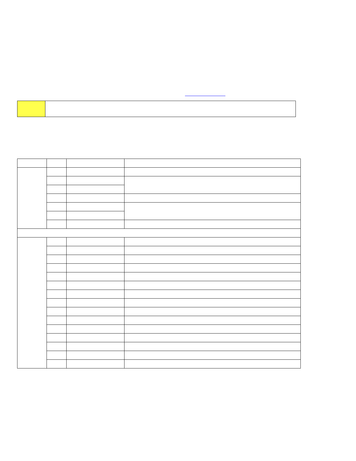
Table 7
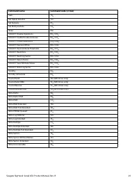
Serial ATA connector pin definitions
Segment
Pin
Function
Definition
Signal
S1
Ground
2nd mate
S2
A+
Differential signal pair A from Phy
S3
A-
S4
Ground
2nd mate
S5
B-
Differential signal pair B from Phy
S6
B+
S7
Ground
2nd mate
Key and spacing separate signal and power segments
Power
P1
V
33
3.3V power
P2
V
33
3.3V power
P3
V
33
3.3V power, pre-charge, 2nd mate
P4
Ground
1st mate
P5
Ground
2nd mate
P6
Ground
2nd mate
P7
V
5
5V power, pre-charge, 2nd mate
P8
V
5
5V power
P9
V
5
5V power
P10
Ground
2nd mate
P11
Ground or LED signal
If grounded, drive does not use deferred spin
P12
Ground
1st mate.
P13
V
12
12V power, pre-charge, 2nd mate
P14
V
12
12V power
P15
V
12
12V power
Характеристики

Остались вопросы?Не нашли свой ответ в руководстве или возникли другие проблемы? Задайте свой вопрос в форме ниже с подробным описанием вашей ситуации, чтобы другие люди и специалисты смогли дать на него ответ. Если вы знаете как решить проблему другого человека, пожалуйста, подскажите ему :)
