Ноутбуки DELL Vostro 5635 (N1004VNB5635UA_W11P) - инструкция пользователя по применению, эксплуатации и установке на русском языке. Мы надеемся, она поможет вам решить возникшие у вас вопросы при эксплуатации техники.
Если остались вопросы, задайте их в комментариях после инструкции.
"Загружаем инструкцию", означает, что нужно подождать пока файл загрузится и можно будет его читать онлайн. Некоторые инструкции очень большие и время их появления зависит от вашей скорости интернета.
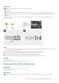
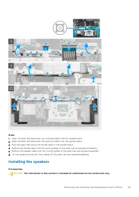
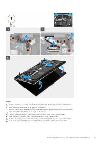
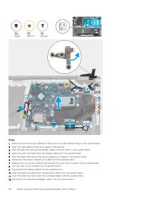


13. Replace the two screws (M2x4) that secure the Type-C port-bracket to the system board.
14. Connect the power-adapter port cable to the system board.
15. Adhere the tapes that secure the power-adapter port cable to the system board.
16. Connect the display cable from the system board and close the latch.
17. Adhere the tape that secures the display-cable connector latch to the system board.
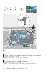
18. Connect the power-adapter port cable to the system board.
19. Adhere the tapes that secure the power-adapter port cable to the system board.
20. Connect the display cable to the system board and close the latch.
21. Adhere the tape that secures the display-cable connector latch to the system board.
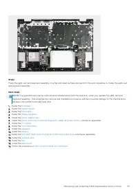
22. Close the right display hinge and align the screw holes on the right display hinge with the screw holes on the palm-rest and
keyboard assembly.
23. Replace the three screws (M2.5x5) that secure the right display hinge to the palm-rest and keyboard assembly.
Next steps
1. Install the
.
2. Install the
.
3. Install the
or
, whichever applicable.
4. Install the
5. Follow the procedure in
After working inside your computer
.
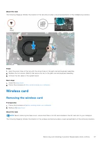
Touchpad
Removing the touchpad
Prerequisites
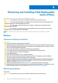
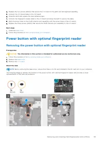
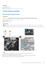
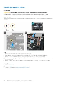
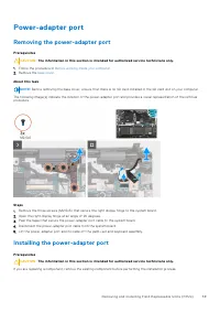
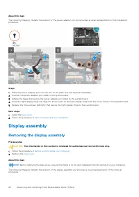
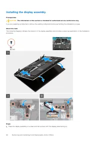
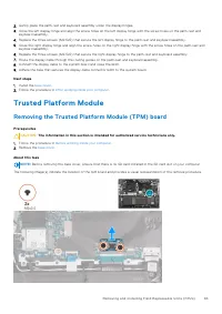
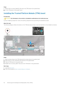
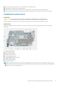
CAUTION:
The information in this section is intended for authorized service technicians only.
1. Follow the procedure in
Before working inside your computer
2. Remove the
.
3. Remove the
.
About this task
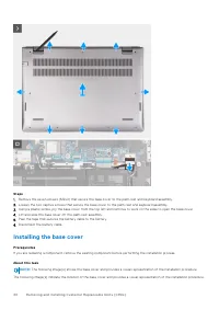
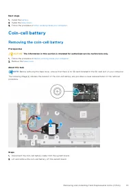
NOTE:
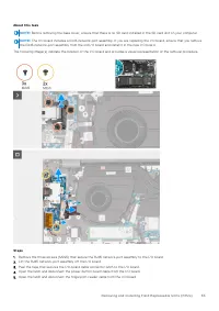
Before removing the base cover, ensure that there is no SD card installed in the SD card slot on your computer.
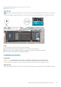
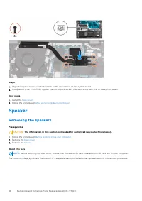
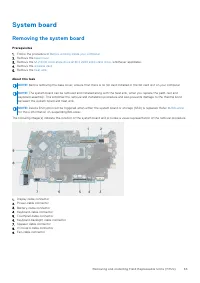
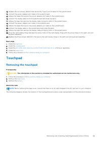
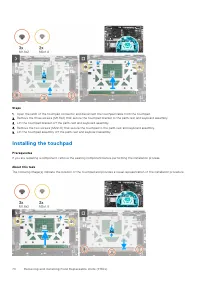
The following image(s) indicate the location of the touchpad and provides a visual representation of the removal procedure.
Removing and installing Field Replaceable Units (FRUs)
69
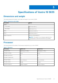
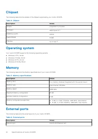
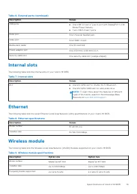
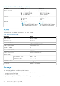
Характеристики

Остались вопросы?Не нашли свой ответ в руководстве или возникли другие проблемы? Задайте свой вопрос в форме ниже с подробным описанием вашей ситуации, чтобы другие люди и специалисты смогли дать на него ответ. Если вы знаете как решить проблему другого человека, пожалуйста, подскажите ему :)


