
Мультиметры TOPEX 94W101 - инструкция пользователя по применению, эксплуатации и установке на русском языке. Мы надеемся, она поможет вам решить возникшие у вас вопросы при эксплуатации техники.
Если остались вопросы, задайте их в комментариях после инструкции.
"Загружаем инструкцию", означает, что нужно подождать пока файл загрузится и можно будет его читать онлайн. Некоторые инструкции очень большие и время их появления зависит от вашей скорости интернета.

16
TOPEX.PL
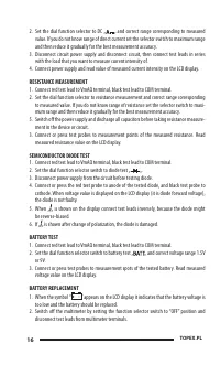
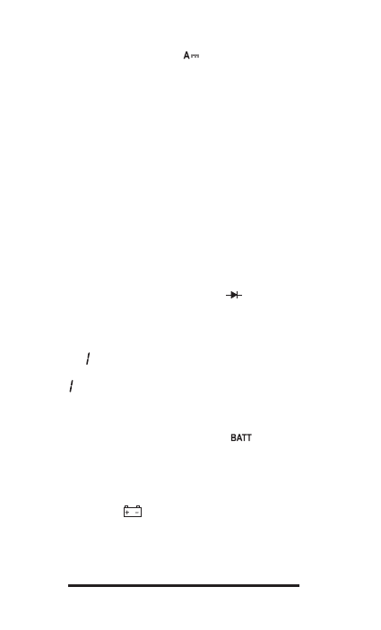
2. Set the dial function selector to DC „
„ and correct range corresponding to measured
value. If you do not know range of direct current set the selector switch to maximum range
and then reduce it gradually for the best measurement accuracy.
3. Disconnect circuit power supply and disconnect circuit, then connect test leads in series
with the load that you want to measure current intensity of.
4. Connect power supply and read value of measured current intensity on the LCD display.
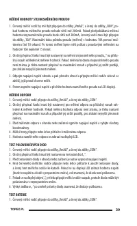
RESISTANCE MEASUREMENT
1. Connect red test lead to VmAΩ terminal, black test lead to COM terminal.
2. Set the dial function selector to resistance measurement and correct range corresponding
to measured value. If you do not know range of resistance set the selector switch to maxi-
mum range and then reduce it gradually for the best measurement accuracy.
5. Switch off the power supply and discharge all capacitors before taking resistance measure-
ment in the device or circuit.
3. Connect or press test probes to measurement points of the measured resistance. Read
measured resistance value on the LCD display.
SEMICONDUCTOR DIODE TEST
1. Connect red test lead to VmAΩ terminal, black test lead to COM terminal.
2. Set the dial function selector switch to diode test „
„.
3. Disconnect power supply from the circuit before testing diode.
4. Connect or press the red test probe to anode of the tested diode, and black test probe to
cathode. When voltage value is displayed on the LCD display (it is diode forward voltage),
the diode is not faulty.
5. When „ „ is shown on the display connect test leads inversely, because the diode might
be reverse-biased.
6. If „ „ is shown after change of polarization, the diode is damaged.
BATTERY TEST
1. Connect red test lead to VmAΩ terminal, black test lead to COM terminal.
2. Set the dial function selector switch to battery test „
„ and correct voltage range 1.5V
or 9V.
3. Connect or press test probes to measurement spots of the tested battery. Read measured
voltage value on the LCD display.
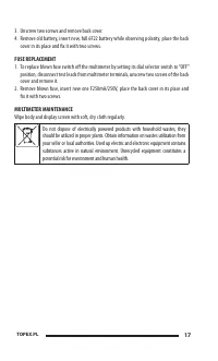
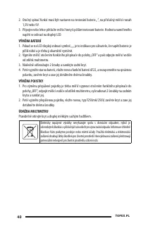
BATTERY REPLACEMENT
1. When the symbol “
“ appears on the LCD display it indicates that the battery voltage is
too low and the battery should be replaced.
2. Switch off the multimeter by setting the function selector switch to “OFF” position and
disconnect test leads from multimeter terminals.
Содержание
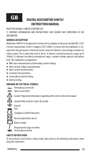
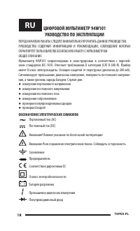
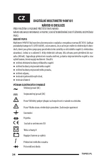
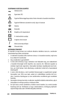
- 18 УКОВОДСТВО ПО ЭКСПЛУАТАЦИИ; ОБОЗНАЧЕНИЕ ЭЛЕКТРИЧЕСКИХ СИМВОЛОВ
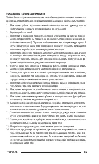
- 19 УКАЗАНИЯ ПО ТЕХНИКЕ БЕЗОПАСНОСТИ; эксплуатации и соблюдать все содержащиеся в нем указания.
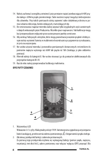
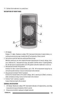
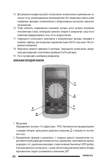
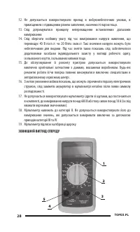
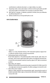
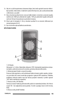
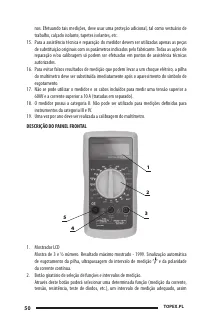
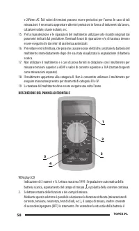
- 20 ОПИСАНИЕ ПЕРЕДНЕЙ ПАНЕЛИ
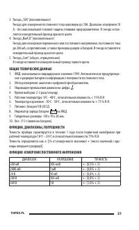
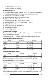
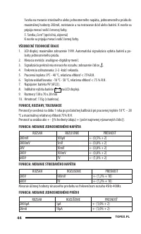
- 21 В гнездо вставляется измерительный провод черного цвета.; ОБЩИЕ ТЕХНИЧЕСКИЕ ДАННЫЕ; ДИАПАЗОН
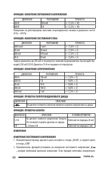
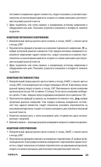
- 23 „ выбрав; ИЗМЕРЕНИЕ СОПРОТИВЛЕНИЯ
- 25 УХОД; Периодически протирать корпус и дисплей сухой мягкой тряпочкой.


