
Мультиметры DEFORT DMM-1000N 98298123 - инструкция пользователя по применению, эксплуатации и установке на русском языке. Мы надеемся, она поможет вам решить возникшие у вас вопросы при эксплуатации техники.
Если остались вопросы, задайте их в комментариях после инструкции.
"Загружаем инструкцию", означает, что нужно подождать пока файл загрузится и можно будет его читать онлайн. Некоторые инструкции очень большие и время их появления зависит от вашей скорости интернета.


10
GB
1000 V peak value (constantly in all ranges).
Display: Corrected centre point corresponds to the ef-
fective value in a sinusoidal form.)
HINT:
1. In case the voltage range is unknown, you must set
the FUNCTION switch in the highest measurement
range and then reduce the range gradually if required.
2. If the
fi
gure «I» now appears on the display, the
measurand lies outside the range set. The FUNC-
TION switch must be switched to a higher range.
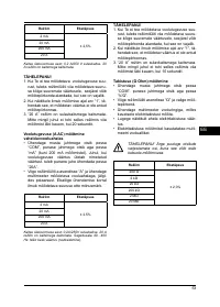
3. The maximum input voltage is 750 VAC effective
value. Higher voltages cannot be measured.
4. Proceed extremely cautiously with the measure-
ment of high voltages.
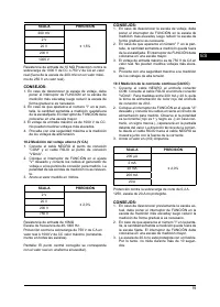
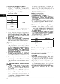
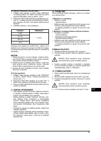
10.3 MEASURING DIRECT CURRENT (ADC)
1. Connect the BLACK lead to the COM connector
socket. Connect the RED lead to the «V
Ω
mA» con-
nector socket. For measurements between 200mA
and 20 A, remove RED lead to «20 A» connector
socket.
2. Set the FUNCTION switch on the desired «A» set-
ting and connect the leads in series to the power
circuit to be measured. Observe correct polar-
ity (red is + and black is -), otherwise the display
shows a minus sign before the value. The techni-
cal current direction of the RED lead to the BLACK
lead is displayed at the same time with the current
strength.
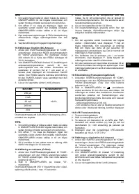
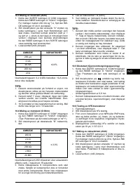
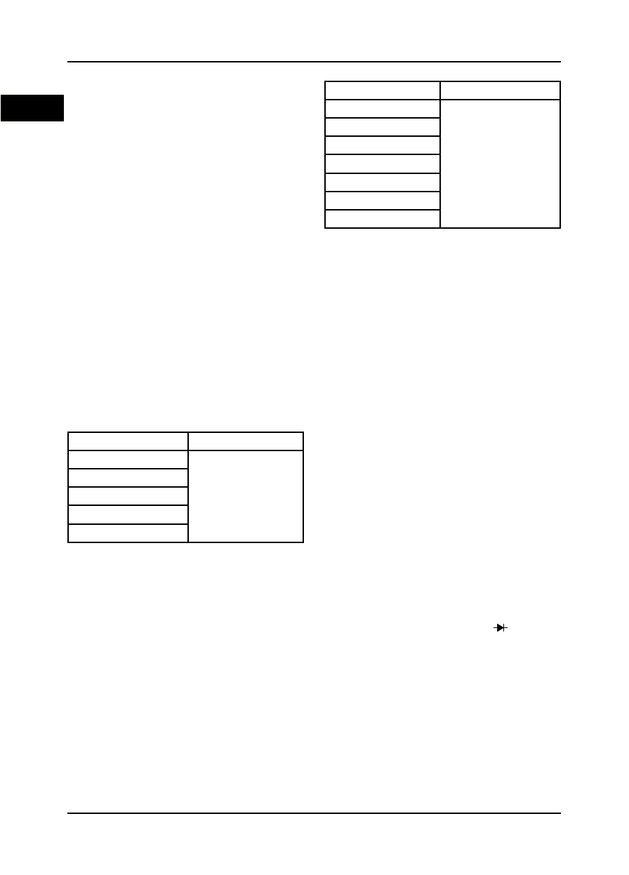
3. Read off the value in (milli-) Ampere.
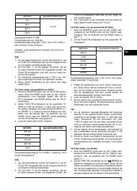
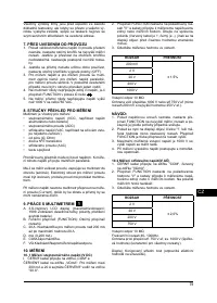
RANGE
ACCURACY
200
η
A
± 2,0%
2 mA
20 mA
200 mA
20 A
Overload protection 0.2 A/250-V cut-out, 20-A-range
not protected.
HINT:
1. In case the current range is previously unknown,
you must set the FUNCTION switch in the highest
measurement range and then reduce the measure-
ment range gradually if required.
2. If the
fi
gure «I» now appears on the display, the
measurand lies outside the set measurement
range. The FUNCTION switch must be switched to
a higher measurement range.
3. The 20 A range is not protected with a fuse. Do not,
therefore, measure for longer than 10 seconds.
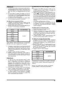
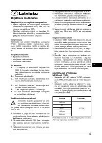
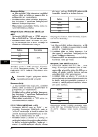
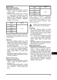
10.4 MEASURINGTHE RESISTANCE (
Ω
Ohm)
1. Connect the BLACK lead to the «COM» connector
socket and the RED lead to the «V
Ω
mA» connec-
tor socket. (Hint: The polarity of the red lead is then
«+».)
2. Setthe FUNCTION switch on the desired «
Ω
»
measuring range.
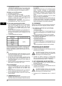
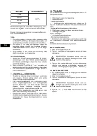
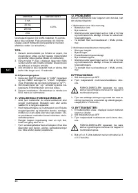
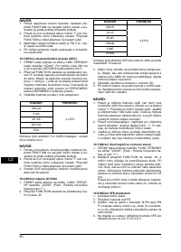
RANGE
ACCURACY
200
Ω
± 2,0%
200
Ω
2 K
Ω
20 K
Ω
200 K
Ω
2 M
Ω
20 M
Ω
Overload protection 250 V DC or AC Effective value,
for maximum 15 seconds
3. Connect the measuring tips to the components to
be measured. Ensure that the component is not
linked to the other components. Do not touch the
measuring tips so as not to affect resistance val-
ues.
4. Read off the measured value in
Ω
(Ohm).
5. While measuring the resistances, current from the
internal battery is used. This current consumption
differs according to the set measurement range.
HINT:
1. n case the measurand exceeds the highest value in
the set measurement range, the display shows «I».
Select a higher measurement range. If the resist-
ance is about 1 M
Ω
and higher, the measuring de-
vice can take a couple of seconds to stabilise. This
is normal in the measurement of high resistances.
2. If the input is not connected, say in a broken power
circuit, the display shows the
fi
gure «I». This means
that the measurement falls outside the range.
3. In case the resistance to be measured is connected
to a power circuit, you must switch off the voltage
before beginning the measurement and see that all
capacitors are discharged.
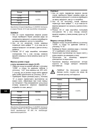
10.5 DIODES MEASUREMENT
(CONDUCTING-STATE VOLTAGE)
1. Connect the BLACK lead to the «COM» connector
socket and the RED lead to the «V
Ω
mA» connec-
tor socket. (Hint: The polarity of the red lead is then
«+».)
2. Setthe FUNCTION switch on the
-range and
connect the measuring tips to the diode to be
measured. In the measurement of diodes or tran-
sistors, the polarity of the measuring tips deter-
mines whether the forward direction or the blocking
direction is measured. The displayed value is the
conducting-state voltage drop.
-
The tripping current is 0.8 mA.
-
In case the measuring tips are not or wrongly con-
nected to the diode i.e. in the blocking direction, the
display shows the
fi
gure I.
10.6 HFE-TRANSISTOR MEASUREMENT
1. Remove the measuring cable.


