Материнские платы GIGABYTE H610 - инструкция пользователя по применению, эксплуатации и установке на русском языке. Мы надеемся, она поможет вам решить возникшие у вас вопросы при эксплуатации техники.
Если остались вопросы, задайте их в комментариях после инструкции.
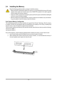
"Загружаем инструкцию", означает, что нужно подождать пока файл загрузится и можно будет его читать онлайн. Некоторые инструкции очень большие и время их появления зависит от вашей скорости интернета.
- 19 -
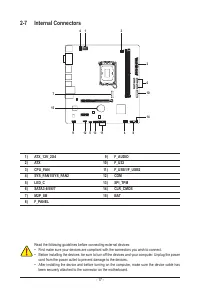
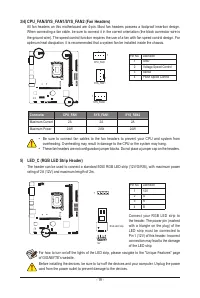
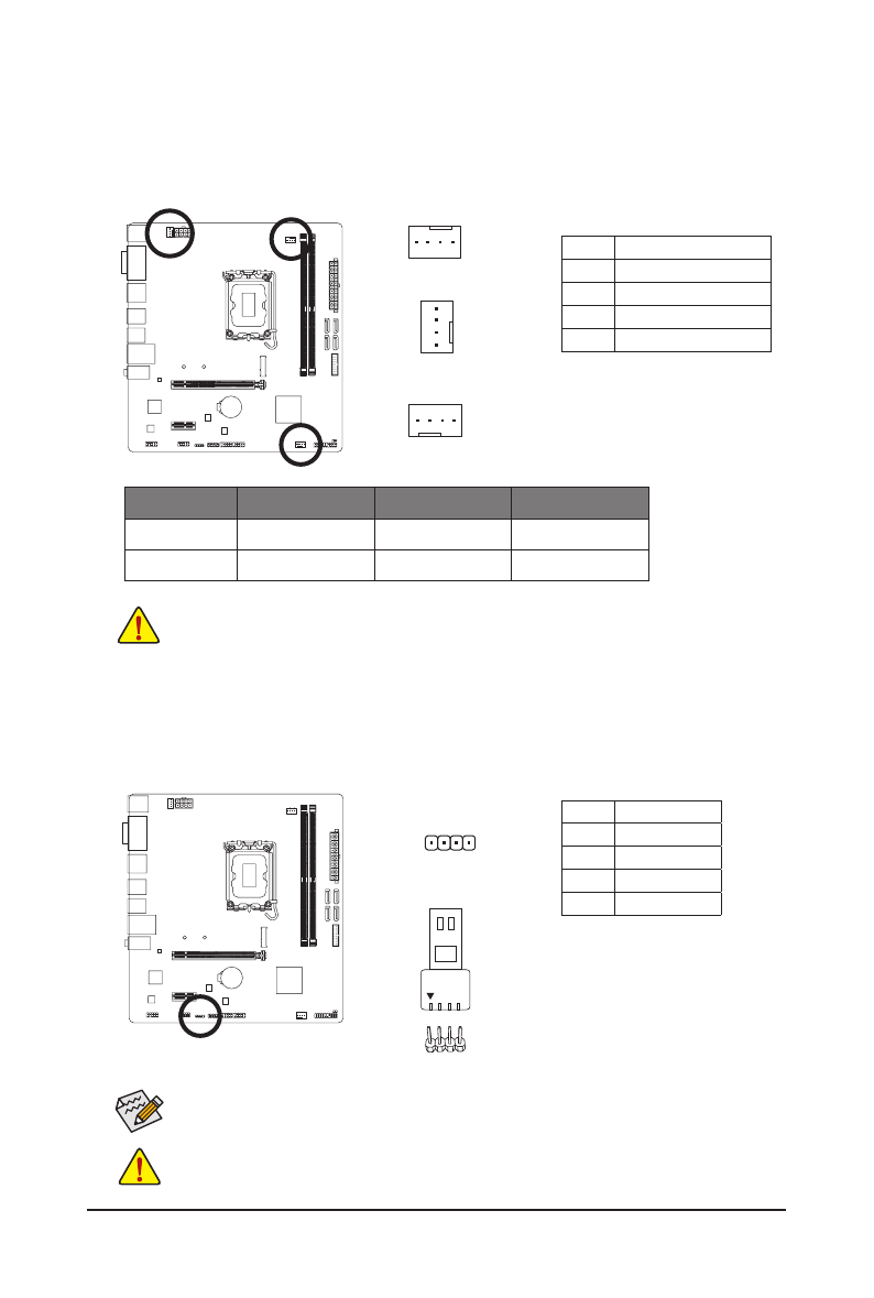
3/4) CPU_FAN/SYS_FAN1/SYS_FAN2 (Fan Headers)
All fan headers on this motherboard are 4-pin. Most fan headers possess a foolproof insertion design.
When connecting a fan cable, be sure to connect it in the correct orientation (the black connector wire is
the ground wire). The speed control function requires the use of a fan with fan speed control design. For
optimum heat dissipation, it is recommended that a system fan be installed inside the chassis.
Pin No.
Definition
1
GND
2
Voltage Speed Control
3
Sense
4
PWM Speed Control
DEBUG
PORT
G.QBOFM
DEBUG
PORT
G.QBOFM
1
CPU_FAN
1
DEBUG
PO
RT
G.QBOFM
1
SYS_FAN1
SYS_FAN2
•
Be sure to connect fan cables to the fan headers to prevent your CPU and system from
overheating. Overheating may result in damage to the CPU or the system may hang.
•
These fan headers are not configuration jumper blocks. Do not place a jumper cap on the headers.
Connector
CPU_FAN
SYS_FAN1
SYS_FAN2
Maximum Current
2A
2A
2A
Maximum Power
24W
24W
24W
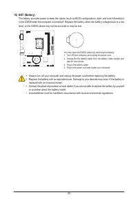
Before installing the devices, be sure to turn off the devices and your computer. Unplug the power
cord from the power outlet to prevent damage to the devices.
For how to turn on/off the lights of the LED strip, please navigate to the "Unique Features" page
of GIGABYTE's website.
5) LED_C (RGB LED Strip Header)
The header can be used to connect a standard 5050 RGB LED strip (12V/G/R/B), with maximum power
rating of 2A (12V) and maximum length of 2m.
Pin No.
Definition
1
12V
2
G
3
R
4
B
1
DEBUG
PORT
G.QBOFM
RGB LED Strip
1
12V
Connect your RGB LED strip to
the header. The power pin (marked
with a triangle on the plug) of the
LED strip must be connected to
Pin 1 (12V) of this header. Incorrect
connection may lead to the damage
of the LED strip.
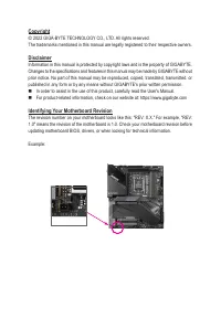
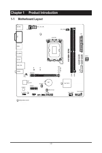
Характеристики

Остались вопросы?Не нашли свой ответ в руководстве или возникли другие проблемы? Задайте свой вопрос в форме ниже с подробным описанием вашей ситуации, чтобы другие люди и специалисты смогли дать на него ответ. Если вы знаете как решить проблему другого человека, пожалуйста, подскажите ему :)


