Источники бесперебойного питания APC (XB005XPDR) - инструкция пользователя по применению, эксплуатации и установке на русском языке. Мы надеемся, она поможет вам решить возникшие у вас вопросы при эксплуатации техники.
Если остались вопросы, задайте их в комментариях после инструкции.
"Загружаем инструкцию", означает, что нужно подождать пока файл загрузится и можно будет его читать онлайн. Некоторые инструкции очень большие и время их появления зависит от вашей скорости интернета.
Safety and General Instructions
SAVE THESE INSTRUCTIONS - This manual contains important instructions that should
be followed during installation and maintenance of the product.
Read the user documentation to become familiar with the equipment before
trying to install or operate it.
• While disconnecting wires, be sure to disconnect the wires at battery pack(s) first and
then at the power supply unit.
• Always connect the wires to the power supply unit first and then to battery pack(s).
• Use RED color wire for +ve and BLACK color wire for –ve connections.
• Use insulated pin type lugs to be sure that the wire strands do not touch any metallic
surface during connection/disconnection.
• Be sure that the wires do not touch any metallic surface during
connection/disconnection.
• Allow minimum space of 50 mm above the battery pack and 180 mm below the battery
pack and 10 mm lateral distance from other devices to be sure of sufficient cooling.
• CAUTION: The enclosure can reach temperatures that exceed the burn thresholds for
touchable surfaces, depending on the ambient temperature and load.
• Do not introduce any objects into the device.
Specifications
Environmental
Physical
Battery
Certification and Standards
IEC/EN/BS/UL 62368-1, CSA-C22.2 No. 62368-1, IEC/EN 60950-1, CE, UKCA, cTUVus
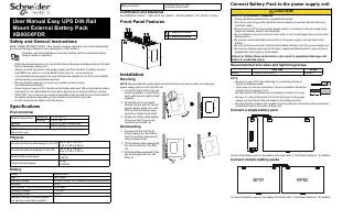
Front Panel Features
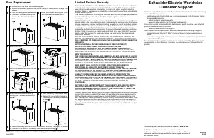
Installation
Mounting
NOTE
: Be sure that the input/output terminal blocks are at the top while mounting the
power supply unit on a 35 mm DIN rail.
1. Locate the top hooks of the rail
mounting system (on the battery
pack) with the unit slightly tilted
upwards.
2. Rotate the unit in clockwise
direction till the latch of the rail
mount system snaps on to the
DIN rail and the battery pack
cannot be rotated any further.
3. Shake the battery pack slightly
to be sure that it is securely
mounted on the DIN rail.
Dismounting
1. Release the latch of the rail
mount system (on the battery
pack) by pulling it downwards
using a screw driver.
2. Tilt the battery pack upwards till
the latch is free from the DIN
rail.
3. Slide the battery upwards till the
top hooks gets free from the
DIN rail.
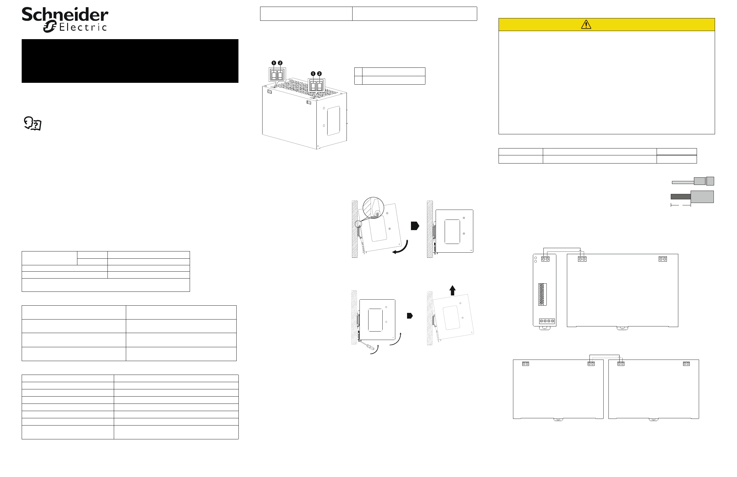
Connect Battery Pack to the power supply unit
Recommended wire sizes and tightening torque
NOTE
:
• Be sure to use a Pin Type cable lug for connecting the Input,
Output and Battery wires.
• To be sure of a secure connection, the wire insulation should be
stripped (S) for approx. 6 mm,
Be sure that all the strands are completely enclosed in the lug.
• Be sure to connect the wires first to the terminals on the power
supply unit and then to the terminals on the battery pack(s).
• Be sure that the positive and negative polarity wires are connected to the respective
output terminals on the power supply unit.
Connect a single battery pack
Connect the battery wires to the battery terminals (refer “Front Panel Features” for details).
Connect mutiple battery packs
Connect the battery wires to the battery terminals (refer “Front Panel Features” for details).
Ambient temperature
Operating
–15 to +50 °C
Storage*
–15 to +40 °C
Humidity
0 to 95% (Non condensing)
Altitude
3000 m (Max.)
NOTE
: * Charge the battery once in every 3 months during storage or
when not in use.
Dimensions without packaging (H x W x D)
192 x 129 x 119 mm
(7.56 x 5.08 x 4.69 in)
Dimensions with packaging (H x W x D)
240 x 190 x 188 mm
(9.45 x 7.48 x 7.40 in)
Weight without packaging
4.5 kg
(9.92 lb)
Weight with packaging
4.8 kg
(10.58 lb)
Model
XB005XPDR
Type
SMF VRLA
Nominal Voltage
24 VDC (2 Nos. 12 V batteries connected in series)
Capacity
4.5 Ah
Over current / Short circuit protection 40 A Fuses
Charging Voltage
27.4 VDC
Charging Current
0.75 A
Maximum number of battery packs
that can be connected in parallel
4
Battery Runtime
10 minutes at 10 A load
3 minutes at 20 A load
(+) Battery terminal
(–) Battery terminal
o
em
0348
a
oem
0349a
o
em
0 3
50
a
CAUTION
RISK OF EQUIPMENT DAMAGE
• Wiring should be performed by a qualified electrician.
• Wire size must comply with required current capacity as well as national and local
electrical codes.
• Be sure to turn
Off
the input power supply before connecting or disconnecting input,
output and battery wires to the terminals.
• Be sure that the wires do not touch each other or any metal object during connection/
disconnection.
• Be sure to connect the battery wires first to the power supply unit and then to the
battery.
• Be sure to disconnect wires first from the battery and then from the power supply unit.
• Be sure to crimp pin type lugs to the input, output and battery wires to prevent loose
strands from touching any metal object.
Failure to follow these instructions can result in equipment damage and
minor or moderate injury.
Wire Size
Torque
Battery
12 AWG (3.310 mm
2
)
0.8 N m
s
+ –
+ –
+ –
o
em
0
35
1a
BP#1
BP#2
+ –
+ –
+ –
+ –
oe
m
035
2a
User Manual Easy UPS DIN Rail
Mount External Battery Pack
XB005XPDR
Характеристики

Остались вопросы?Не нашли свой ответ в руководстве или возникли другие проблемы? Задайте свой вопрос в форме ниже с подробным описанием вашей ситуации, чтобы другие люди и специалисты смогли дать на него ответ. Если вы знаете как решить проблему другого человека, пожалуйста, подскажите ему :)


