
Холодильник Liebherr CU 3503 - инструкция пользователя по применению, эксплуатации и установке на русском языке. Мы надеемся, она поможет вам решить возникшие у вас вопросы при эксплуатации техники.
Если остались вопросы, задайте их в комментариях после инструкции.
"Загружаем инструкцию", означает, что нужно подождать пока файл загрузится и можно будет его читать онлайн. Некоторые инструкции очень большие и время их появления зависит от вашей скорости интернета.
17
8 Instructions for installation and modification
The
external dimensions of the appliance can be seen on
fig.
S.
Do not install the appliance side-by-side with another refri-
gerator or freezer. This is important to prevent condensation
and consequential damage from it.
All types and models are subject to continuous improvement
and the manufacturer therefore reserves the right to make
modifications in the shape, equipment and technology.
Before reading, please fold out and
refer to the illustrated back page.
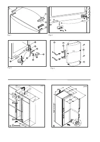
Changing over door hinges
You can change over the door hinges if necessary:
Make sure that the following tools are at hand:
- Torx 25
- Torx 15
- Screwdriver
- Cordless screwdriver, if required
Screw off the upper bearing block
- Close the upper door.
- Remove cover Fig. 1 (1) and cover Fig. 1 (2).
- Screw off the upper bearing block Fig. 1 (3) (2 mal Torx 25)
Fig. 1 (4) and lift upwards.
CAREFUL!
Danger of injury when the door tilts outwards!
- Hold the door well.
- Carefully set down the door.
Removing the upper door
- Lift off the upper door upwards and set aside.
- Lift the plug Fig. 4 (30) out of the upper door bearing bush
and set down.
Removing the lower door
- Close the lower door.
- Pull off the plastic cap Fig. 2 (10).
- Pull out the centre bearing bolt Fig. 2 (11).
- Remove the door upwards and set aside.
- Lift the plug Fig. 4 (30) out of the lower door bearing bush
and re-locate.
Re-locate the centre bearing components
- Pull off the cover panel Fig. 2 (12).
- Screw off the centre bearing block Fig. 2 (13) and relocate
to the new hinge side by turning by 180°.
- Engage the cover panel Fig. 2 (12) on the new handle side.
Re-locate the lower bearing components
- Remove the lower cover Fig. 3 (21) forwards.
- Remove the lower cover Fig. 3 (22) downwards and
forwards.
In doing so, pay attention to the hinge bush Fig. 3 (20).
- Screw off the bearing block Fig. 3 (23) (3 x Torx 25) Fig. 3 (24).
- Screw off the bearing component Fig. 3 (26) (1 x Torx 25)
Fig. 3 (27) and re-locate it into the opposite mounting hole,
then firmly screw in again.
- Lift off and re-locate the cover on the handle side Fig. 3 (25).
- Screw the bearing block Fig. 3 (23) back onto the new
hinge side.
Fit the lower door
- Place the door onto the bottom bearing bolt from the top
Fig. 3 (22).
- Close the door.
- Install the centre bearing bolt Fig. 2 (11) on the new hinge
side into the lower door through the centre bearing block
Fig. 2 (13).
- Place the plastic cap Fig. 2 (10) turned by 180° back onto
the centre bearing block Fig. 2 (13).
Fit the upper door
- Place the upper door onto the centre bearing bolt Fig. 2 (11).
- Install the upper bearing block Fig. 1 (3) on the new hinge
side and in the door.
- Screw the upper bearing block Fig. 1 (2 x Torx 25) Fig. 1
(4) in tightly.
- Engage cover Fig. 1 (1) and cover Fig. 1 (2) respectively
on the opposite side.
Re-locate the handles
- Disengage the spring clamp Fig. 4 (31) from the fridge
section door and re-locate on the new hinge side.
- Dismantle the door handles Fig. 4 (32), plugs Fig. 4 (33)
and pressure plates
Dismantle Fig. 4 (34) with the door open.
- Ensure proper engagement when fitting the pressure
plates.
- Align the doors flush with the appliance housing possibly
via the two slotted holes in the lower bearing block Fig. 3
(23) and the centre bearing block Fig. 2 (13), then firmly
tighten the screws.
- Engage the cover Fig. 3 (21) again.
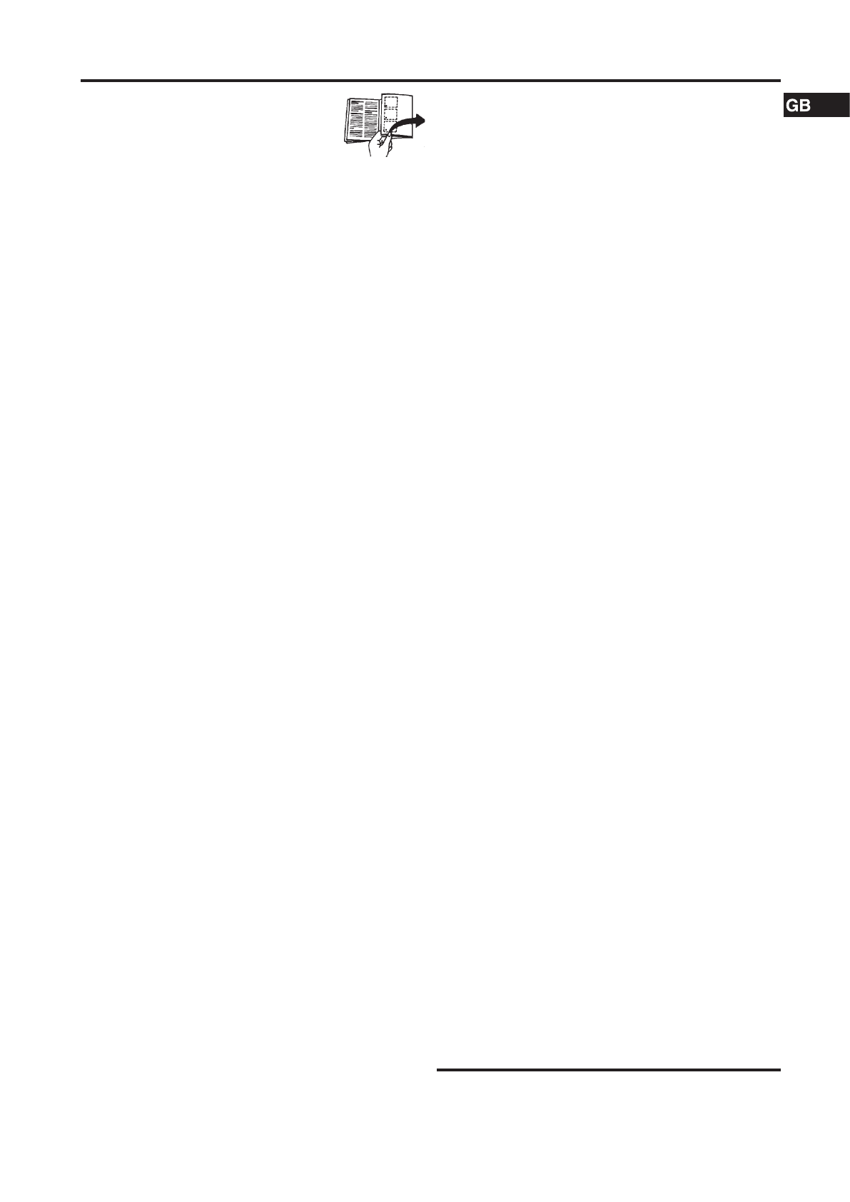
Insertion into row of kitchen units
1
top unit
2
refrigerator/freezer
3
Kitchen cupboard
4
wall
Fig.
U: The appliances can be installed in a row of kitchen
units. To adapt the height of the appliance to the surrounding
furniture a top unit
1
can be added.
When retrofitting with standard kitchen cabinets (max. depth
580 mm), the appliance can be set up directly next to the
kitchen cupboard Fig.
U
3
. The appliance door protrudes
34 mm at the side and 50 mm in the middle of the appliance
against the front panel of the kitchen cupboard. It can
therefore be opened and closed without any problems.
Important for ventilation:
- On the rear side of the top unit there must be a ventilation
duct of at least 50 mm depth along the entire width of the
top unit.
- The area of ventilation underneath the ceiling must be at
least 300 cm².
- The larger the ventilation cross section, the more energy
the appliance will be able to save.
If the appliance is installed with the hinge side against a wall
Fig.
U
4
, the distance between the appliance and the wall
must be at least 36 mm. This corresponds with the handle
protrusion when the door is open.
Характеристики

Остались вопросы?Не нашли свой ответ в руководстве или возникли другие проблемы? Задайте свой вопрос в форме ниже с подробным описанием вашей ситуации, чтобы другие люди и специалисты смогли дать на него ответ. Если вы знаете как решить проблему другого человека, пожалуйста, подскажите ему :)


