Condtrol Maxwell 4 - Инструкция по эксплуатации
Измерительный прибор Condtrol Maxwell 4 - инструкция пользователя по применению, эксплуатации и установке на русском языке. Мы надеемся, она поможет вам решить возникшие у вас вопросы при эксплуатации техники.
Если остались дополнительные вопросы — свяжитесь с нами через контактную форму.
1
Max well 4
User manual
Infrared thermometer
EN
Congratulations on your purchase of infrared thermometer
Maxwell 4 CONDTROL.
Safety instructions given in this user manual should be
carefully read before you use the product for the first time.
S A F E T Y R EG U L AT I O N S
Attention! This user manual is an essential par t of this product.
The user manual should be read carefully before you use the
product for the first time. If the product is given to someone
for temporar y use, be sure to enclose user manual to it.
- Do not misuse the product
- Do not remove warning signs and protect them from
abrasion, because they contain information about safe
operation of the product.
Laser radiation!
Do not stare into beam
Class 2 laser
<1 mW 630 -670nm
EN60825-1: 2007- 03
- Do not look into the laser beam or its reflection, with
unprotected eye or through an optical instrument. Do not
point the laser beam at people or animals without the need.
You can dazzle them.
- To protect your eyes close them or look aside.
- Do not let unauthorized people enter the zone of product
operation.
- Store the product beyond reach of children and unauthorized
people.
- It is prohibited to disassemble or repair the product yourself.
Entrust product repair to qualified personnel and use original
spare par ts only.
- Do not use the product in explosive environment, close to
flammable materials.
- Avoid heating the batteries to avoid the risk of explosion and
electroly te leakage. In case of liquid contact with skin, wash
it immediately with soap and water. In case of contact with
eyes, flush with clean water during 10 minutes and consult the
doctor.
Max well 4
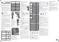
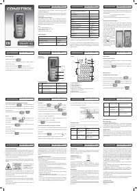
1 - Ambient temperature value
2 - Relative humidity value
3 - Surface temperature value
4 - Measuring unit - Fahrenheit
5 - Measuring unit – degrees Celsius
6 - Batter y charge level
7 - Indication of activated laser point
8 - Indication of active measurement
9 - Indication of temperature beyond the set limit
(temperature is below the limit)
10 - Indication of temperature beyond the set limit
(temperature is above the limit)
11 - Indication of data hold on the display
12 - Emissivity value
OPERATION
Install/replace the batteries
Open the batter y cover. Install the batteries obser ving correct
polarity. Put the batter y cover back and push it until a click is
heard.
If the symbol of low batter y change
level appears on the display, replace the
batteries by new ones.
Switch on/off
Shor t press the trigger to switch the device
on.
The device is ready to work.
The device switches of f automatically in 30
seconds af ter the last press on any button.
1) Laser point
Shor t press the button , to activate the laser point*.
Symbol will appear on the display. Shor t press the button
to switch of f the laser point. Symbol will disappear
from the display. Laser point is only used for aiming and can
be switched of f when working at shor t distance to save the
batter y power.
*Laser point is on as long as the trigger is pressed.
2) Display backlight
Shor t press the button to switch on/of f the display
backlight.
3) Indication of temperature beyond the set limit
High temperature alarm limit
Press and hold the button
MODE
during 2 seconds to enter
parameter setting mode. Symbol
Hi
will appear on the display.
Shor t press the buttons and to adjust the high
temperature alarm limit. To exit the parameter setting mode
shor t press the trigger or press and hold the button
MODE
during 3 seconds.
Low temperature alarm limit
Press and hold the button
MODE
during 2 seconds to enter
parameter setting mode. Shor t press the button
MODE
to select the setting of low temperature alarm limit (Low).
Symbol
Low
will appear on the display. Shor t press the
buttons and to adjust the low temperature
alarm limit. To exit the parameter setting mode shor t press the
trigger or press and hold the button
MODE
during 3 seconds.
FUNCTIONS/APPLICATIONS
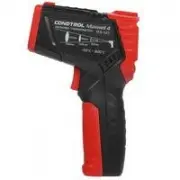
Infrared thermometer Maxwell 4 CONDTROL is designed
to measure object ’s surface temperature by non-contact
method. It is equipped with temperature and humidity sensors
as well as an infrared sensor for object surface temperature
measurement, which can detect the «cold bridges» and places
where mildew can form. One touch on the trigger allows to
identif y poorly insulated areas in windows or to detect leaking
areas in external walls.
PACKAGE
Infrared thermometer Maxwell 4 – 1pc.
Power supply (1.5V A A A) - 2 pcs.
User manual - 1 pc.
TECHNICAL SPECIFICATIONS
Measuring range of
object temperature
-30 °С…550 °С
-22 °F…1022 °F
Accuracy of surface
temperature
-30 °С...0 °С /
-22 °F…32 °F
0 °С....550 °С /
32 °F…1022 °F
±3 °С
±(1,5% + 2 °С)
measurement
Measuring range of
ambient temperature
-10 °C…60 °C (14 °F…140 °F)
Accuracy of ambient
temperature
measurement
-10 °C…0 °C
(14 °F…32 °F)
±1.5 °C/3 °F
0 °C…40°C
(32 °F…113 °F)
±1.0 °C/2 °F
40 °C…60°C
(113 °F…140 °F)
±1.5 °C/3 °F
Measuring range of
relative humidity
0% …100% RH
Accuracy of relative
humidity measurement
0%...20%: ±5.0% RH
20%...80%: ±4.0% RH
80%...100%: ±5.0% RH
Optical resolution
12:1
Response time
<0.5 sec
Automatic shutdown
30 sec
Spectral sensitivity
8...14 µm
Emissivity
0.1…1.0 adjustable
Working temperature
0°С …40°С
Storage temperature
-10°С…60°С
Relative humidity
10...95% for operation
< 80% for storage
Power supply
2 x 1.5V A A A alkaline
Laser
Class II, 630 -670 nm, <1 mW
Dimensions
148 x 102 x 46 mm
Weight
130 g
PRODUCT DESCRIPTION
Infrared thermometer
Инфракрасный пирометр
EN
RU
EN User manual 1
RU Руководство пользователя 2
4) Emissivity
All objects emit thermal energy. The volume of radiated
energy depends on the surface temperature
and emissivity of the object. The IR-thermometer measures
the intensity of radiation and
uses it to calculate the temperature of the object. Objects with
dif ferent surfaces but
equal temperature emit dif ferent amount of thermal energy.
Most of the objects and materials, for example, painted
metals, wood, water, leather, fabric have a high emissivity
(0.9 and more) and emit more energy than shiny surfaces and
unpainted metals with emissivity less than 0.6. Adjustment
of emissivity allows the device to take it into account and to
minimize the measurement error.
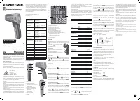
Table 1. Emissivity of materials
Material
Emissivity
Aluminum
Oxidized
0.2~ 0.4
Oxidized allow
0.3
Rough alloy
0.1~ 0.3
Brass
Polished
0.3
Oxidized
0.5
Copper
Oxidized
0.4~ 0.8
Electronic terminal board 0.6
Hastelloy
0.3~ 0.8
Chromium-
nickel-iron alloy
Oxidized
0.7~ 0.95
Sandblast
0.3~ 0.6
Electro polished
0.15
Iron
Oxidized
0.5~ 0.9
Rusted
0.5~ 0.7
Iron (cast)
Oxidized
0.6~ 0.95
Unoxidized
0.2
Melt and cast
0.2~ 0.3
Iron forged passivated
0.9
Lead
Rough
0.4
Oxidized
0.2~ 0.6
Molybdenum oxidized
0.2~ 0.6
Nickel oxidized
0.2~ 0.5
Platinum black
0.9
Steel
Cold rolled
0.7~ 0.9
Sanding plate
0.4~ 0.6
Polished plate
0.1
Zinc
Oxidized
0.1
Asbestos
0.95
Asphalt
0.95
Basalt stone
0.7
Carbon
0.8~ 0.9
Graphite
0.9
Silicon carbide
0.95
Clay
0.95
Concrete
0.95
Fabric
0.95
Glass plate
0.85
Sand gravel
0.95
Gypsum
0.8~ 0.95
Ice
0.98
Limestone
0.98
Paper
0.95
Plastic
0.95
Soil
0.9~ 0.98
Water
0.93
Wood (natural)
0.9~ 0.95
Press and hold the button
MODE
during 2 seconds to enter
parameter setting mode. Press the button
MODE
2 times.
Symbol
will appear on the display. Shor t press the
buttons and to adjust the emissivity value.
To exit the parameter setting mode shor t press the trigger or
press and hold the button
MODE
during 3 seconds.
1
2
4
5
3
8
9
6
7
8
9
1 - LED indicator
2 - Display
3 - Button for activation/
deactivation of the laser point/
adjustment of emissivity
(decrease value)
4 - Button for parameter setting
5 - Button for switching on/of f
LCD backlight/
adjustment of emissivity
(increase value)
6 - Laser exit window
7 - Infrared sensor
8 - Trigger
9 - Batter y cover
11
10
9
8
7
6
12
2
3
5
4
9
5) Measuring unit
Press and hold the button
MODE
during 2 seconds to enter
parameter setting mode. Shor t press the button
MODE
3 times. Symbol
0
C
will appear on the display. Shor t press
the buttons and to select the measuring unit
(°C – degrees Celsius / °F – Fahrenheit degree). To exit the
parameter setting mode shor t press the trigger or press and
hold the button
MODE
during 3 seconds.
Measurements
Switch on the device. Aim the device at the object of
measurement and press the trigger. Keep the trigger
pressed to enter continuous measurement. Symbol of active
measurement will appear on the display. Measurement
results will appear on the display in real time mode.
If measurement result is beyond the set limit, LED indicator
turns red, the symbol
Hi
or
Low
appears on the display. When
the trigger is released, the device keeps the last measured
values on the display. The symbol appears on the display.
OPTICAL RESOLUTION
As the distance from the device to the object increases, the
size of the measured spot on object surface increases as well.
To determine the size of the spot (S) you need to divide the
distance from the device to the target (D) by 12.
Laser points ser ve as the reference to determine the size and
position of measured spot.
125 84 42 - spot (S)
1500 1000 500 - distance (D)
CARE AND MAINTENANCE
Attention! The product is an accurate optical mechanic device
and requires careful handling. Maintenance of the following
recommendations will extend the life of the device:
- Keep the product clean and protected from any bumps, dust
and dampness; do not allow getting moisture, dust or other
dir t inside of the product.
- Do not expose the product to extreme temperatures.
- If liquids get inside the product first remove the batteries,
then contact a ser vice center
- Do not store or use the product under high humidity
conditions for a long time.
- Clean the product with sof t wet cloth.
- Keep the device optics clean and protect it from mechanical
impact.
Failure to obser ve the following rules may result in leakage of
electroly te from the batteries and damage the device:
- Remove the batteries from the product if you do not use it
for a long time.
- Do not leave discharged batteries in the device.
UTILIZATION
Expired tools, accessories and package should be passed
for waste recycle. Please send the product to the following
address for proper recycle:
CONDTROL GmbH
Wasserburger Strasse 9
84427 Sankt Wolfgang
Germany
Do not throw the product in municipal waste!
According to European directive 2002/96/ЕC expired
measuring tools and their components must be collected
separately and submitted to environmentally friendly recycle
of wastes.
WARRANT Y
All CONDTROL GmbH products go through post-production
control and are governed by the following warranty terms. The
buyer ’s right to claim about defects and general provisions of
the current legislation do not expire.
1) CONDTROL GmbH agrees to eliminate all defects in the
product, discovered while warranty period, that represent the
defect in material or workmanship in full volume and at its own
expense.
2) The warranty period is 24 months and star ts from the date
of purchase by the end customer (see the original suppor ting
document).
3) The warranty doesn’t cover defects resulting from wear
and tear or improper use, malfunction of the product caused
by failure to obser ve the instructions of this user manual,
untimely maintenance and ser vice and insuf ficient care, the
use of non-original accessories and spare par ts. Modifications
in design of the product relieve the seller from responsibility
for warranty works. The warranty does not cover cosmetic
damage, that doesn’t hinder normal operation of the product.
4) CONDTROL GmbH reserves the right to decide on replacement or
repair of the device.
5) Other claims not mentioned above, are not covered by the warranty.
6) After holding warranty works by CONDTROL GmbH warranty period is
not renewed or ex tended.
7) CONDTROL GmbH is not liable for loss of profit or inconvenience
associated with a defect of the device, rental cost of alternative
equipment for the period of repair.
This warranty applies to German law except provision of the United
Nations Convention on contracts for the international sale of goods
(CISG).
In warranty case please return the product to retail seller or send it with
description of defect to the following address:
CONDTROL GmbH
Wasserburger Strasse 9
84 427 Sankt Wolfgang
Germany
Display
1
"Загрузка инструкции" означает, что нужно подождать пока файл загрузится и можно будет его читать онлайн. Некоторые инструкции очень большие и время их появления зависит от вашей скорости интернета.
Была ли эта инструкция полезной?
Об этой инструкции
- Бренд
- Condtrol
- Модель
- Maxwell 4
- Тип документа
- Инструкция по эксплуатации
- Категория
- Измерительный прибор
- Язык(и)
- Русский
- Страницы
- 2
- Размер файла
- 1,3 MB
- Формат
Задать вопрос
Похожие инструкции
Ещё модели: измерительные приборы Condtrol
 Condtrol XP4 Инструкция по эксплуатации
 Condtrol 24X Инструкция по эксплуатации
- Condtrol 32X Инструкция по эксплуатации
 Condtrol GFX360 Инструкция по эксплуатации
- Condtrol GFX360-3 Инструкция по эксплуатации
 Condtrol Maxwell 3 Инструкция по эксплуатации
 Condtrol Neo X1-360 Инструкция по эксплуатации
 Condtrol Neo X200 Инструкция по эксплуатации
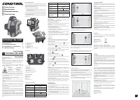 Condtrol Omniliner G3D Инструкция по эксплуатации
 Condtrol QB Инструкция по эксплуатации
- Condtrol QB Green Инструкция по эксплуатации
- Condtrol QB promo Инструкция по эксплуатации
 Condtrol Smart 40 Инструкция по эксплуатации
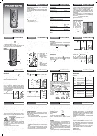 Condtrol Smart 60 Инструкция по эксплуатации
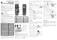 Condtrol Vector 30 Инструкция по эксплуатации
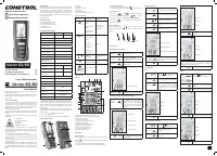 Condtrol Vector 60 Инструкция по эксплуатации
- Condtrol Vector 80 Инструкция по эксплуатации
 Condtrol Vector 100 Инструкция по эксплуатации
 Condtrol X1 LE Инструкция по эксплуатации
 Condtrol X2 Инструкция по эксплуатации