APC Easy - Инструкция по эксплуатации
Источник бесперебойного питания APC Easy - инструкция пользователя по применению, эксплуатации и установке на русском языке. Мы надеемся, она поможет вам решить возникшие у вас вопросы при эксплуатации техники.
Если остались дополнительные вопросы — свяжитесь с нами через контактную форму.
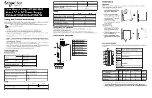
Safety and General Instructions
SAVE THESE INSTRUCTIONS - This manual contains important instructions that should
be followed during installation and maintenance of the product.
Read the user documentation to become familiar with the equipment before
trying to install or operate it.
• Switch off the input power before connecting or disconnecting the wires.
• Use RED color wire for +ve and BLACK color wire for –ve connections.
• Use insulated pin type lugs to be sure that the wire strands do not touch any metallic
surface during connection/disconnection.
• Be sure that the wires do not touch any metallic surface during connection/
disconnection.
• Be sure to connect the wires to the power supply unit first and then to battery pack(s).
• While disconnecting wires, be sure to disconnect the wires at battery pack(s) first and
then at the power supply unit.
• Allow a minimum space of 50 mm above the unit, 180 mm below the unit and 10 mm
lateral distance from other devices to be sure of sufficient cooling.
• CAUTION: The enclosure can reach temperatures that exceed the burn thresholds for
touchable surfaces, depending on the ambient temperature and load.
• Do not introduce any objects into the power supply unit.
Specifications
Environmental
Physical
Input
Output
Certification and Standards
IEC/EN/BS/UL 62368-1, CSA-C22.2 No. 62368-1, IEC/EN 60950-1, UL 508,
CSA C22.2 No. 14, IEC/EN 61010-1.
cTUVus CE, UKCA, GB 4943.1, CQC, EN 55032, EN55035, EN IEC 61000-6-2,
EN IEC 61000-6-4, EN IEC 61204-3, FCC 47 CFR Part 15, Subpart B & ICES-003 Issue 7
Front Panel Features
Installation
Mounting
NOTE
: Be sure that the input/output terminal block is at the bottom while mounting the
power supply unit on a 35 mm DIN rail.
1. Locate the top hook of the rail
mounting system (on the unit)
with the unit slightly tilted
upwards.
2. Rotate the unit in clockwise
direction till the latch of the rail
mount system snaps on to the
DIN rail and the unit cannot be
rotated any further.
3. Shake the unit slightly to be
sure that it is securely mounted
on the DIN rail.
Dismounting
1. Release the latch of the rail
mount system (on the unit) by
pulling it downwards using a
screw driver.
2. Tilt the unit upwards till the latch
is free from the DIN rail.
3. Slide the unit upwards till the
top hook gets free from the DIN
rail.
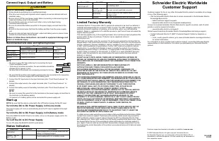
Dry contact details
All dry contacts (Pin3 to Pin10) are normally closed during operation and will open during
an event.
NOTE:
• NC = Normally Closed; NO = Normally Open; NA = Not Applicable.
• To insert wires into the Dry Contact terminals, press the locking lever (
) using a
suitable screwdriver and insert the wire into the terminal (
). Remove the screwdriver
to secure the wire to the terminal.
Ambient temperature
Operating
–15 to +50 °C
Storage
–15 to +70 °C
Humidity
5 to 95% (Non condensing)
Altitude
Operating
3000 m (Max.)
Storage
3000 m (Max.)
Audible Noise
< 40 db
International Protection Code
IP 20
Operating Protection Class
Class II
Dimensions without packaging (H x W x D)
129 x 40 x 119 mm
(5.08 x 1.57 x 4.69 in)
Dimensions with packaging (H x W x D)
190 x 57x 188 mm
(7.47 x 2.23 x 7.39 in)
Weight without packaging
0.5 kg
(1.1 lb)
Weight with packaging
0.7 kg
(1.54 lb)
240 W
480 W
Model
BVS240XDPDR
BVS480XDPDR
Nominal input voltage
24 VDC
Voltage Range
21.6 – 28.6 VDC
Nominal Current
10 A
20 A
Runtime at full load (with 1 battery pack)
10 min at 10 A load 3 min at 20 A load
Efficiency at Nominal Voltage (Bypass mode,
battery fully charged)
>95%
Over current / Short circuit protection
40 A Fuse
240 W
480 W
Nominal output voltage U
N
/ tolerance
24 VDC
Switch On time (On delay time typical)
< 1 s
Output current
10 A
20 A
Output over current limit
10.5 A< OCP<13 A
20.5 A<OCP<26 A
Short circuit protection
Yes
Over temperature protection
Yes
No. of units series connection
No
No. of units parallel connection
No
(+) Battery terminal
(–) Battery terminal
(–) Output terminal
(+) Output terminal
(–) Input terminal
(+) Input terminal
Dry contact terminals
Status LED - Red
Status LED - Green
240 W
480 W
o
em
034
3a
Pin1
Remote On/Off. Connect Normally Open
Push to On button to this contact.
Pin2
Pin3
On-Battery mode
Pin4
Pin5
Replace battery
Pin6
Pin7
Battery disconnected
Pin8
Pin9
Low battery
Pin10
Locking lever
Terminal
Mode of Operation
→
Line
Mode
Battery
Mode
Battery Mode
Low Battery
Line Mode
Battery disconnected
Replace
Battery
Condition
↓
Remote On/Off
NA
NA
NA
NA
NA
On-Battery
NC
NO
NO
NC
NC
Replace Battery
NC
NC
NC
NC
NO
Battery Disconnected
NC
NC
NC
NO
NC
Low Battery
NC
NC
NO
NC
NC
oem
0
344a
o e
m
03
4 5
a
oem0346a
User Manual Easy UPS DIN Rail
Mount DC to DC Power Supply
BVS240XDPDR/BVS480XDPDR
"Загрузка инструкции" означает, что нужно подождать пока файл загрузится и можно будет его читать онлайн. Некоторые инструкции очень большие и время их появления зависит от вашей скорости интернета.
Была ли эта инструкция полезной?
Об этой инструкции
- Бренд
- APC
- Модель
- Easy
- Тип документа
- Инструкция по эксплуатации
- Категория
- Источник бесперебойного питания
- Язык(и)
- Русский
- Страницы
- 2
- Размер файла
- 188,5 KB
- Формат
Задать вопрос
Похожие инструкции
Популярные источники бесперебойного питания APC
Ещё модели: источники бесперебойного питания APC
 APC Back-UPS Pro BR900MI Инструкция по эксплуатации
 APC Back-UPS Pro BR1300MI Инструкция по эксплуатации
 APC Back-UPS Pro BR1600MI Инструкция по эксплуатации
 APC Back UPS Pro BR 1600VA Инструкция по эксплуатации
 APC BR500 Инструкция по эксплуатации
 APC BR1000I BR800I Инструкция по эксплуатации
 APC Easy-UPS BV800I Инструкция по эксплуатации
 APC Easy-UPS BV1000I Инструкция по эксплуатации
 APC Easy UPS BV 650VA Инструкция по эксплуатации
 APC Easy UPS BV 800VA Инструкция по эксплуатации
 APC Easy UPS BV 1000VA Инструкция по эксплуатации
 APC Panel Инструкция по эксплуатации
 APC SC450 Инструкция по эксплуатации
 APC Smart-UPS 750VA Инструкция по эксплуатации
 APC Smart-UPS 1500VA Инструкция по эксплуатации
 APC Smart-UPS C SMC3000I Инструкция по эксплуатации