AEG FRTD 903 - Инструкция по эксплуатации
AEG FRTD 903 - инструкция пользователя по применению, эксплуатации и установке на русском языке. Мы надеемся, она поможет вам решить возникшие у вас вопросы при эксплуатации техники.
Если остались дополнительные вопросы — свяжитесь с нами через контактную форму.

© 2010 OJ Electronics A/S - EHT Haustechnik GMBH
2
entlasten. Damit leisten wir gemeinsam einen
wichtigen Beitrag zum Umweltschutz.
RECYCLING VON ALTGERÄTEN
Geräte mit diesem Aufkleber dürfen
nicht mit dem normalen Hausmüll
entsorgt werden. Sie müssen
getrennt gesammelt und gemäß den
lokalen Vorschriften entsorgt werden.
TECHNISCHE DATEN
Spannung .................... 230 V AC ± 10%, 50 Hz
Max. Vorsicherung ....................................... 16 A
Eingebauter Schalter ..................... 2-polig, 16 A
Ausgangsrelais ...... Schließkontakt - SPST - NO
Ausgang ............................. Max. 16 A / 3600 W
Regelprinzip ........................................... PBM/PI
Bereitschaftsbetrieb ................................. 0,6 W
Batterie-Backup ..................................... 5 Jahre
Temperaturbereich.............................. +5/+40 °C
Begrenzungsfühler (OCD4) ................. +5/+40 °C
Umgebungsbetriebstemperatur ......... +0/+25 °C
Energie auslesung, genauigkeit ................... 2%
Verschmutzungsgradkontrolle .......................... 2
Nennimpulsspannung ................................. 4 kV
Schutzgrad .................................................. IP21
Abmessungen .................. H/84, B/84, T/40 mm
Einbautiefe ............................................... 20 mm
Display .................................... 100x64 Pixel STN
- Hintergrundbeleuchtung
EU Gebrauchsmuster ........... 001101349-0001/2
Der Thermostat ist wartungsfrei.
English
The thermostat is an electronic on/off thermo-
stat for temperature control by means of an
NTC sensor located either externally or inter-
nally within the thermostat.
The thermostat is for flush mounting in a wall
socket. A baseplate for external wall mounting
is available.
PRODUCT PROGRAMME
FRTD 903
(MCD4-1999) Clock-thermostat with 2 sensors.
Floor sensor and built-in room
sensor.
WARNING
– Important Safety Instructions.
Disconnect the power supply before carrying
out any installation or maintenance work on this
control unit and associated components. This
control unit and associated components should
only be installed by a competent person (i.e. a
qualified electrician). Electrical installation must
be in accordance with appropriate statutory
regulations.
MOUNTING OF SENSOR
The floor sensor contains a safety extra-low
voltage (SELV) circuit, allowing it to be placed
as close to the floor surface as necessary with-
out having to take account of the risk of shock
should the sensor cable become damaged. The
two wires from the sensor to the mounting box,
must be additionally insulated, e.g. shrink flex.
To prevent loose cables from the fixed instal-
lation from coming into contact with the
terminal block for the floor sensor, they must be
restrained using cable ties.
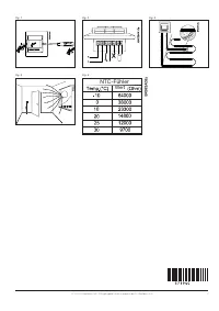
It is recommended that the cable and sensor be
placed in a non-conductive installation pipe em-
bedded in the floor (fig. 3). The end of the pipe
must be sealed and the pipe placed as high as
possible in the concrete layer. Alternatively, the
sensor can be embedded directly in the floor.
The sensor cable must be led through a sepa-
rate pipe or segregated from power cables.
The floor sensor must be centred between the
heating cable.
The sensor cable may be extended up to 7 m
by means of a separate two-core cable. Two
vacant wires in a multi-core cable used, for
example, to supply current to the floor heating
cable must not be used. The switching peaks
of such current supply lines may create inter-
ference signals that prevent optimum controller
function. If a shielded cable is used, the shield
must not be connected to earth (PE). The two-
core cable must be placed in a separate pipe or
segregated from power cables.
MOUNTING OF THERMOSTAT
WITH BUILT-IN SENSOR
The room sensor is used for comfort tempera-
ture regulation in rooms. The thermostat should
be mounted on the wall approx. 1.6 m above
the floor in such a way as to allow free air circu-
lation around it. Draughts and direct sunlight or
other heat sources must be avoided (fig. 4). No
external sensor is connected.
Mounting of thermostat
1. Slide the power button down to Off “0”.
2. Release the front cover ONLY by inserting a
small screwdriver into the hole on either side
of the thermostat.
3. Connect the wires in accordance with the
diagram (fig. 2).
4. Mount the thermostat in the wall socket.
5. Fit the frame and carefully press the cover
onto the thermostat. Ensure that both the
power slide button on the cover and the
power switch pin are down.
DO NOT
open the thermostat by releasing the
four fixing clips on the back.
First time settings:
The first time the thermostat is connected,
push the power slide button to On “I”. Lan-
guage, time and date must be set using the
buttons:
1. Set language
2. Set time
3. Set date
PROGRAMMING
See user manual.
FAULT LOCATION
If the sensor is disconnected or short-circuited,
the heating system is switched off. The sensor
can be checked against the resistance table
(fig. 5).
ERROR CODES
E0: Internal error. The thermostat must be
replaced.
E1: Built-in sensor short-circuited or
disconnected.
E2: External sensor short-circuited or
disconnected.
E5: Internal overheating. Inspect the installa-
tion.
CE MARKING
According to the following standard:
LVD/EMC: EN 60730-2-9
CLASSIFICATION
The product is a Class II device (enhanced
insulation) and must be connected to in the
following way:
Term. 1: Neutral (N
Term. 2: Phase (L) 230 V ±10%, 50/60 Hz
Term. 3–4: Load, max. 16 A / 3600 W
Term. X: Do not connect
Term. 5-6: External floor sensor
ENVIRONMENT AND RECYCLING
Please help us to protect the environment by
disposing of the packaging in accordance with
national regulations for waste processing.
RECYCLING OF OBSOLETE APPLIANCES
Appliances with this label must not
be disposed of with general
household waste. They must be
collected separately and disposed
of in compliance with local
regulations.
TECHNICAL DATA
Voltage ............................ 230 VAC ±10% 50 Hz
Max. pre-fuse .............................................. 16 A
Built-in circuit breaker .................... 2-pole, 16 A
Output relay ............. Make contact - SPST - NO
Output ................................ Max. 16 A / 3600 W
Control principle .................................... PWM/PI
Stand-by power ........................................ 0.6 W
Battery backup ....................................... 5 years
Temperature range .............................. +5/+40°C
Limit sensor (OCD4) ............................ +5/+40°C
Ambient operating temperature ........... +0/+25°C
Control pollution degree ................................... 2
Rated impulse voltage ................................. 4 kV
Enclosure rating .......................................... IP 21
Dimensions ...................... H/84, W/84, D/40 mm
Build-in depth .......................................... 20 mm
Display ........ 100x64 pixel STN - white backlight
EU Registered Design ........ 001101349-0001/2
The thermostat is maintenance free.
Русский
Термостат представляет собой электронный
термостат для регулирования температуры
путем включения / отключения нагрузки при
помощи термодатчика NTC, расположенного
снаружи или внутри термостата.
Термостат монтируется в стенной коробке
(утопленный монтаж). Можно приобрести
крепежное основание для наружного мон-
тажа.
НОМЕНКЛАТУРА ИЗДЕЛИЙ
FRTD 903
(MCD4-1999) Термостат с контролем времени
с 2 датчиками. Датчик тем-
пературы пола и встроенный
датчик температуры воздуха в
помещении.
ОСТОРОЖНО
– Важные указания по технике
безопасности. Прежде чем приступать к мон-
тажу или техническому обслуживанию этого
прибора и связанных с ним компонентов, от-
ключите электропитание. Монтаж этого при-
бора и связанных с ним компонентов должен
производить только профессионал (например,
квалифицированный электрик). Электромон-
таж должен быть выполнен с соблюдением
действующих правил в этой области.
МОНТАЖ ДАТЧИКА
Датчик температуры пола содержит цепь
безопасного сверхнизкого напряжения
(SELV), что позволяет размещать его сколь
угодно близко к поверхности пола без необ-
ходимости учитывать опасность поражения
электрическим током в случае повреждения
кабеля датчика. Два провода, ведущих от
датчика к монтажной коробке, нужно до-
полнительно заизолировать, например, при
помощи трубчатых оболочек shrink flex.
Свободные кабели, идущие от неподвижного
места монтажа, следует связать ремешками
для того, чтобы предотвратить возможность
их контакта с клеммной колодкой датчика
температуры пола.
Рекомендуется размещать кабель и датчик
в монтажной трубе из диэлектрического
материала, заложенной в пол (рис. 3). Конец
этой трубы герметично заделывается, а
сама труба размещается как можно выше в
"Загрузка инструкции" означает, что нужно подождать пока файл загрузится и можно будет его читать онлайн. Некоторые инструкции очень большие и время их появления зависит от вашей скорости интернета.
Была ли эта инструкция полезной?
Об этой инструкции
- Бренд
- AEG
- Модель
- FRTD 903
- Тип документа
- Инструкция по эксплуатации
- Язык(и)
- Немецкий, Английский, Французский, Dutch, Польский, Русский, Swedish
- Страницы
- 6
- Размер файла
- 517,5 KB
- Формат
Задать вопрос
Похожие инструкции
Ещё модели: другое AEG
 AEG Ergomax Инструкция по эксплуатации
 AEG EX 125 E Инструкция по эксплуатации
 AEG EX 150 E Инструкция по эксплуатации
 AEG EZS 5664 Инструкция по эксплуатации
 AEG F55350VI1 Инструкция по эксплуатации
 AEG FDS 140 Инструкция по эксплуатации
 AEG FS 280 Инструкция по эксплуатации
 AEG FT 4919 Инструкция по эксплуатации
 AEG FU 4002 P Инструкция по эксплуатации
 AEG GSL 600 E Инструкция по эксплуатации
 AEG HAS 5582 Инструкция по эксплуатации
 AEG HC3360-M Инструкция по эксплуатации
 AEG HK654070XB Инструкция по эксплуатации
 AEG HR 5625 Инструкция по эксплуатации
 AEG HR 5626 Инструкция по эксплуатации
 AEG HR 5654 Инструкция по эксплуатации
 AEG HTD 5584 Инструкция по эксплуатации
 AEG HVB95450IB Инструкция по эксплуатации
 AEG IAR64413FB Инструкция по эксплуатации
 AEG KDK911424M Инструкция по эксплуатации